Toyota Venza: Installation
INSTALLATION
CAUTION / NOTICE / HINT
NOTICE:
- Do not replace the spiral cable with the battery connected and the ignition switch ON.
- Do not rotate the spiral cable without the steering wheel with the battery connected and the ignition switch ON.
- Ensure that the steering wheel is installed and aligned straight when inspecting the steering sensor.
PROCEDURE
1. INSTALL STEERING SHAKE DAMPER
(a) Install the steering shake damper to the steering wheel sub-assembly with the 2 screws.
Torque:
2.4 N·m {24 kgf·cm, 21 in·lbf}
2. INSTALL CRUISE CONTROL SWITCH WIRE
3. INSTALL CRUISE CONTROL MAIN SWITCH
.gif)
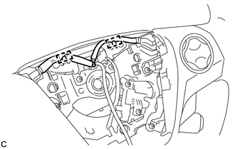
4. INSTALL STEERING PAD SWITCH ASSEMBLY
(a) Engage the 2 claws, 2 pins and 2 guides to install the steering pad switch assembly.
(b) Install the 2 screws.
Torque:
2.4 N·m {24 kgf·cm, 21 in·lbf}
|
(c) Pass the wire harness over the 2 guides. |
|
5. TURN FRONT WHEELS TO FACE STRAIGHT AHEAD
6. ADJUST SPIRAL CABLE WITH SENSOR SUB-ASSEMBLY
7. INSTALL STEERING WHEEL ASSEMBLY
|
(a) Install the steering wheel assembly aligning the matchmarks on the steering wheel assembly and steering main shaft. Text in Illustration
|
|
.png)
(b) Install the steering wheel assembly set nut.
Torque:
50 N·m {510 kgf·cm, 37 ft·lbf}
(c) Connect each connector to the spiral cable sub-assembly.
8. INSPECT STEERING WHEEL CENTER POINT
9. INSTALL STEERING PAD
(See page )
 Removal
REMOVAL
CAUTION / NOTICE / HINT
NOTICE:
Do not replace the spiral cable with the battery connected and the ignition
switch ON.
Do not rotate the spiral cable without the steering wh ...

Other materials about Toyota Venza:
Reassembly
REASSEMBLY
PROCEDURE
1. INSTALL REAR DRIVE SHAFT DUST COVER
(a) Using SST and a steel plate, install a new rear drive shaft dust
cover to the rear drive shaft inboard joint assembly.
Text in Illustration
*1
...
System Diagram
SYSTEM DIAGRAM
Communication Table
Sender
Receiver
Signal
Communication Line
A/C amplifier
ECM
Magnetic clutch request signal*1
CAN
Idle up reques ...
Terminals Of Ecu
TERMINALS OF ECU
1. CHECK POWER BACK DOOR ECU (POWER BACK DOOR MOTOR UNIT)
(a) Disconnect the L20 ECU connector.
(b) Measure the voltage and resistance according to the value(s) in the table
below.
Tester Connection
Wiring Color
...

0.1179