Toyota Venza: Removal
REMOVAL
PROCEDURE
1. REMOVE REAR DOOR SCUFF PLATE
.gif)
2. DISCONNECT REAR DOOR OPENING TRIM WEATHERSTRIP
3. REMOVE TONNEAU COVER ASSEMBLY (w/ Tonneau Cover)
4. REMOVE DECK BOARD ASSEMBLY
5. REMOVE NO. 3 DECK BOARD SUB-ASSEMBLY
6. REMOVE DECK SIDE TRIM BOX LH
7. REMOVE NO. 2 DECK BOARD SUB-ASSEMBLY
8. REMOVE DECK SIDE TRIM BOX RH
9. REMOVE NO. 1 DECK BOARD
10. REMOVE REAR SEAT SUB FLOOR PANEL ASSEMBLY
11. REMOVE REAR FLOOR FINISH PLATE
12. REMOVE REAR SEAT HEADREST ASSEMBLY (for LH Side)
13. REMOVE REAR SEAT INNER TRACK BRACKET COVER (for LH Side)
14. REMOVE REAR SEAT OUTER TRACK BRACKET COVER (for LH Side)
15. DISCONNECT REAR SEAT NO. 2 RECLINING CONTROL CABLE SUB-ASSEMBLY (for LH Side)
16. REMOVE REAR SEAT ASSEMBLY LH (for LH Side)
17. REMOVE REAR SEAT HEADREST ASSEMBLY (for RH Side)
18. REMOVE REAR SEAT CENTER HEADREST ASSEMBLY (for RH Side)
19. REMOVE REAR SEAT INNER TRACK BRACKET COVER (for RH Side)
20. REMOVE REAR SEAT OUTER TRACK BRACKET COVER (for RH Side)
21. DISCONNECT REAR SEAT RECLINING CONTROL CABLE SUB-ASSEMBLY (for RH Side)
22. REMOVE REAR SEAT ASSEMBLY RH (for RH Side)
23. REMOVE RECLINING REMOTE CONTROL BEZEL
24. REMOVE LUGGAGE HOLD BELT STRIKER ASSEMBLY
25. DISCONNECT REAR SEAT OUTER BELT ASSEMBLY
26. REMOVE DECK TRIM SIDE PANEL ASSEMBLY LH (for LH Side)
27. REMOVE DECK TRIM SIDE PANEL ASSEMBLY RH (for RH Side)
28. REMOVE REAR BUMPER PLATE LH
29. REMOVE REAR BUMPER PLATE RH
30. REMOVE REAR BUMPER ASSEMBLY
31. REMOVE REAR COMBINATION LIGHT ASSEMBLY
|
(a) Remove the 2 nuts. |
|
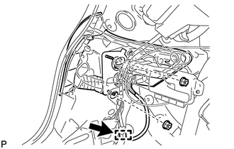
(b) Disconnect the connector.
(c) Disengage the clamp.
|
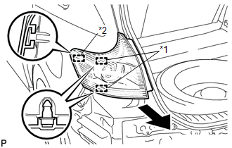
(d) Disengage the 2 pins and guide, and remove the rear combination light assembly as shown in the illustration. Text in Illustration
|
|
 On-vehicle Inspection
ON-VEHICLE INSPECTION
PROCEDURE
1. INSPECT REAR COMBINATION LIGHT ASSEMBLY
(a) Disconnect the connector from the rear combination light assembly.
...
 Disassembly
DISASSEMBLY
PROCEDURE
1. REMOVE TAIL AND STOP LIGHT BULB
(a) Turn the tail and stop light bulb and the rear combination light
socket and wire in the direction indicated by the arrow ...
Other materials about Toyota Venza:
Installation
INSTALLATION
CAUTION / NOTICE / HINT
HINT:
Use the same procedure for the RH side and LH side.
The procedure listed below is for the LH side.
PROCEDURE
1. INSTALL FRONT POWER WINDOW REGULATOR MOTOR ASSEMBLY
NOTICE:
The regulator arm mu ...
Main Body ECU Vehicle Information Reading/Writing Process Malfunction (B15F6)
DESCRIPTION
This DTC is stored when items controlled by the main body ECU (multiplex network
body ECU) cannot be customized via the navigation system vehicle customization screen.
HINT:
The main body ECU (multiplex network body ECU) controls the items ...
Sliding Roof Switch Assembly
Components
COMPONENTS
ILLUSTRATION
Removal
REMOVAL
PROCEDURE
1. REMOVE MAP LIGHT ASSEMBLY
Inspection
INSPECTION
PROCEDURE
1. INSPECT SLIDING ROOF SWITCH (ROOF CONSOLE BOX ASSEMBLY)
(a) Measure the resistance according to the value(s) in ...

0.1306