Toyota Venza: Inspection
INSPECTION
PROCEDURE
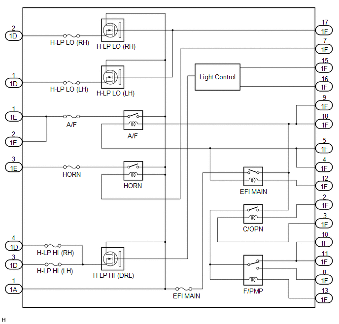
1. INSPECT INTEGRATION RELAY
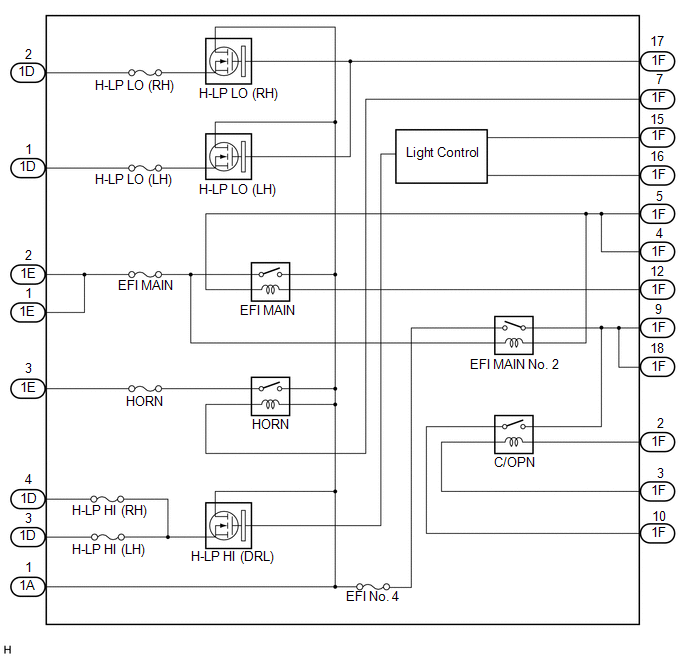
(a) Inner circuit (for 2GR-FE)
|
(1) for EFI MAIN relay
Standard Resistance:
HINT: If the result is not as specified, replace the integration relay. |
|
|
(2) for A/F relay
Standard Resistance:
HINT: If the result is not as specified, replace the integration relay. |
|
|
(3) for F/PMP relay (for AWD)
Standard Resistance:
HINT: If the result is not as specified, replace the integration relay. |
|
|
(4) for C/OPN relay
Standard Resistance:
HINT: If the result is not as specified, replace the integration relay. |
|
|
(5) for HORN relay
Standard Voltage:
HINT: If the result is not as specified, replace the integration relay. |
|
(6) for H-LP LO (LH) relay
- Measure the voltage according to the value(s) in the table below.
Standard Voltage:
|
Tester Connection |
Condition |
Specified Condition |
|---|---|---|
|
1D-1 - Body ground |
Battery positive (+) - 1A-1 Battery negative (-) - 1F-17 |
11 to 14 V |
|
1A-1 - 1D-1 |
Always |
Below 1 V |
|
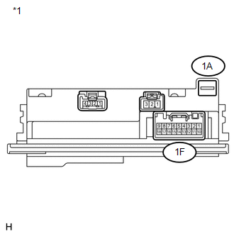
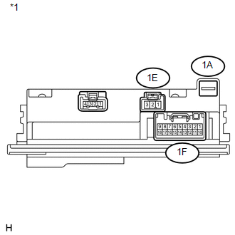
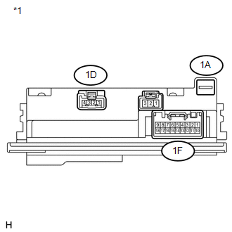
*1 |
Component without harness connected (Integration Relay) |
HINT:
If the result is not as specified, replace the integration relay.
(7) for H-LP LO (RH) relay
- Measure the voltage according to the value(s) in the table below.
Standard Voltage:
|
Tester Connection |
Condition |
Specified Condition |
|---|---|---|
|
1D-2 - Body ground |
Battery positive (+) - 1A-1 Battery negative (-) - 1F-17 |
11 to 14 V |
|
1A-1 - 1D-2 |
Always |
Below 1 V |
|
*1 |
Component without harness connected (Integration Relay) |
HINT:
If the result is not as specified, replace the integration relay.
(8) for H-LP HI (DRL) relay
- for Halogen headlight
- Measure the voltage according to the value(s) in the table below.
Standard Voltage:
Tester Connection
Condition
Specified Condition
1A-1 - 1D-3
Always
Below 1 V
1A-1 - 1D-4
Always
Below 1 V
1F-15 - Body ground
Battery positive (+) - 1A-1
Battery negative (-) - 1F-15
Battery negative (-) - 1F-16
11 to 14 V
1F-15 - Body ground
Battery positive (+) - 1A-1
Battery negative (-) - 1F-15
Battery negative (-) - 1F-16
Pulse generation
1F-16 - Body ground
Battery positive (+) - 1A-1
Battery negative (-) - 1F-15
Battery negative (-) - 1F-16
11 to 14 V
1F-16 - Body ground
Battery positive (+) - 1A-1
Battery negative (-) - 1F-15
Battery negative (-) - 1F-16
Pulse generation
- Measure the voltage according to the value(s) in the table below.
- for HID headlight
- Measure the voltage according to the value(s) in the table below.
Standard Voltage:
Tester Connection
Condition
Specified Condition
1A-1 - 1D-3
Always
Below 1 V
1A-1 - 1D-4
Always
Below 1 V
1F-15 - Body ground
Battery positive (+) - 1A-1
Battery negative (-) - 1F-15
Battery negative (-) - 1F-16
Pulse generation
1F-16 - Body ground
Battery positive (+) - 1A-1
Battery negative (-) - 1F-15
Battery negative (-) - 1F-16
Pulse generation
- Measure the voltage according to the value(s) in the table below.
|
*1 |
Component without harness connected (Integration Relay) |
HINT:
If the result is not as specified, replace the integration relay.
(b) Inner circuit (for 1AR-FE)
|
(1) for EFI MAIN No. 2 relay
Standard Resistance:
HINT: If the result is not as specified, replace the integration relay. |
|
|
(2) for EFI MAIN relay
Standard Resistance:
HINT: If the result is not as specified, replace the integration relay. |
|
|
(3) for C/OPN relay
Standard Resistance:
HINT: If the result is not as specified, replace the integration relay. |
|
|
(4) for HORN relay
Standard Voltage:
HINT: If the result is not as specified, replace the integration relay. |
|
(5) for H-LP LO (LH) relay
- Measure the voltage according to the value(s) in the table below.
Standard Voltage:
|
Tester Connection |
Condition |
Specified Condition |
|---|---|---|
|
1D-1 - Body ground |
Battery positive (+) - 1A-1 Battery negative (-) - 1F-17 |
11 to 14 V |
|
1A-1 - 1D-1 |
Always |
Below 1 V |
|
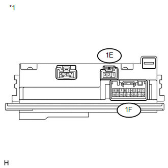
*1 |
Component without harness connected (Integration Relay) |
HINT:
If the result is not as specified, replace the integration relay.
(6) for H-LP LO (RH) relay
- Measure the voltage according to the value(s) in the table below.
Standard Voltage:
|
Tester Connection |
Condition |
Specified Condition |
|---|---|---|
|
1D-2 - Body ground |
Battery positive (+) - 1A-1 Battery negative (-) - 1F-17 |
11 to 14 V |
|
1A-1 - 1D-2 |
Always |
Below 1 V |
|
*1 |
Component without harness connected (Integration Relay) |
HINT:
If the result is not as specified, replace the integration relay.
(7) for H-LP HI (DRL) relay
- for Halogen headlight
- Measure the voltage according to the value(s) in the table below.
Standard Voltage:
Tester Connection
Condition
Specified Condition
1A-1 - 1D-3
Always
Below 1 V
1A-1 - 1D-4
Always
Below 1 V
1F-15 - Body ground
Battery positive (+) - 1A-1
Battery negative (-) - 1F-15
Battery negative (-) - 1F-16
11 to 14 V
1F-15 - Body ground
Battery positive (+) - 1A-1
Battery negative (-) - 1F-15
Battery negative (-) - 1F-16
Pulse generation
1F-16 - Body ground
Battery positive (+) - 1A-1
Battery negative (-) - 1F-15
Battery negative (-) - 1F-16
11 to 14 V
1F-16 - Body ground
Battery positive (+) - 1A-1
Battery negative (-) - 1F-15
Battery negative (-) - 1F-16
Pulse generation
- Measure the voltage according to the value(s) in the table below.
- for HID headlight
- Measure the voltage according to the value(s) in the table below.
Standard Voltage:
Tester Connection
Condition
Specified Condition
1A-1 - 1D-3
Always
Below 1 V
1A-1 - 1D-4
Always
Below 1 V
1F-15 - Body ground
Battery positive (+) - 1A-1
Battery negative (-) - 1F-15
Battery negative (-) - 1F-16
Pulse generation
1F-16 - Body ground
Battery positive (+) - 1A-1
Battery negative (-) - 1F-15
Battery negative (-) - 1F-16
Pulse generation
- Measure the voltage according to the value(s) in the table below.
|
*1 |
Component without harness connected (Integration Relay) |
HINT:
If the result is not as specified, replace the integration relay.
 Components
COMPONENTS
ILLUSTRATION
...
 Removal
REMOVAL
PROCEDURE
1. REMOVE POWER DISTRIBUTION
(a) Remove the bolt.
(b) Disengage the 2 claws and disconnect the power distribution from t ...
Other materials about Toyota Venza:
Transfer Case Front Oil Seal(when Not Using The Engine Support Bridge)
Components
COMPONENTS
ILLUSTRATION
Replacement
REPLACEMENT
PROCEDURE
1. REMOVE TRANSFER ASSEMBLY
(See page ).
2. REMOVE TRANSFER CASE FRONT OIL SEAL
(a) Using SST, remove the transfer case front oil seal from the transfer
case.
...
Terminals Of Ecu
TERMINALS OF ECU
1. CHECK MAIN BODY ECU (DRIVER SIDE JUNCTION BLOCK ASSEMBLY)
(a) Disconnect the 2A, 2C and 2F main body ECU (driver side junction block assembly)
connectors.
(b) Measure the voltage and resistance according to the value(s) in the table ...
Installation
INSTALLATION
PROCEDURE
1. TEMPORARILY TIGHTEN PROPELLER WITH CENTER BEARING SHAFT ASSEMBLY
(a) Remove SST from the transfer.
SST: 09325-20010
(b) Install the propeller with center bearing shaft ...

0.1691