Toyota Venza: Removal
REMOVAL
PROCEDURE
1. DISCONNECT CABLE FROM NEGATIVE BATTERY TERMINAL
NOTICE:
When disconnecting the cable, some systems need to be initialized after the cable
is reconnected (See page .gif) ).
).
2. REMOVE COOL AIR INTAKE DUCT SEAL
3. REMOVE NO. 1 ENGINE COVER SUB-ASSEMBLY
4. REMOVE BATTERY
5. REMOVE INLET AIR CLEANER ASSEMBLY
6. REMOVE STARTER ASSEMBLY
|
(a) Disconnect the starter connector. |
|
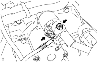
(b) Open the terminal cap, remove the nut and disconnect the starter wire.
|
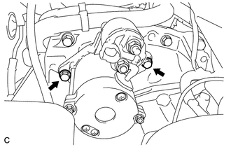
(c) Remove the 2 bolts and starter. |
|
 Components
COMPONENTS
ILLUSTRATION
ILLUSTRATION
...
 Disassembly
DISASSEMBLY
PROCEDURE
1. REMOVE MAGNETIC SWITCH ASSEMBLY
(a) Remove the nut and disconnect the lead wire from the magnetic switch.
...
Other materials about Toyota Venza:
4wd Control Ecu
Components
COMPONENTS
ILLUSTRATION
Removal
REMOVAL
PROCEDURE
1. REMOVE FRONT DOOR SCUFF PLATE RH
2. REMOVE COWL SIDE TRIM SUB-ASSEMBLY RH
3. REMOVE NO. 2 INSTRUMENT PANEL UNDER COVER SUB-ASSEMBLY
4. REMOVE LOWER INSTRUMENT PANEL SUB-ASSEMBLY
...
Precaution
PRECAUTION
1. EXPRESSIONS OF IGNITION SWITCH
The type of ignition switch used on this model differs according to the specifications
of the vehicle.
The expressions listed in the table below are used in this section.
Expression
Switc ...
Engine Speed Signal Error (Test Mode DTC) (C2194/94)
DESCRIPTION
The tire pressure warning ECU receives an engine speed signal from the ECM. This
DTC is stored upon entering signal check mode (test mode), and cleared when an engine
speed signal of 1000 rpm is detected for 3 seconds or more. This DTC is outp ...

0.1155