Toyota Venza: AV Signal Stoppage (Low Battery Voltage) (B158F)
DESCRIPTION
This DTC is stored when a video or audio signal is interrupted due to battery voltage input to the radio and display receiver assembly dropping temporarily.
|
DTC No. |
DTC Detection Condition |
Trouble Area |
|---|---|---|
|
B158F |
A video or audio signal is interrupted when the battery voltage drops |
Radio and display receiver assembly |
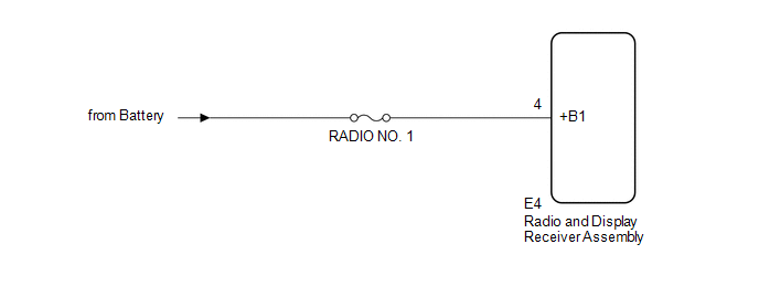
WIRING DIAGRAM
CAUTION / NOTICE / HINT
NOTICE:
Inspect the fuses for circuits related to this system before performing the following inspection procedure.
PROCEDURE
|
1. |
CHECK VEHICLE SIGNAL (OPERATION CHECK) |
|
(a) Enter the "Vehicle Signal Check Mode" screen. Refer to Check Vehicle
Signal in Operation Check (See page |
|
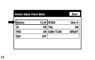
(b) Measure the battery voltage.
Standard Voltage:
11 to 14 V
HINT:
This display is updated once per second.
| NG | .gif) |
GO TO STEP 3 |
|
.gif)
|
2. |
CHECK DTC |
(a) Clear the DTCs (See page .gif) ).
).
(b) Recheck for DTCs and check that no DTCs are output.
OK:
No DTCs are output.
| OK | |
END |
| NG | |
REPLACE RADIO AND DISPLAY RECEIVER ASSEMBLY |
|
3. |
CHECK HARNESS AND CONNECTOR (RADIO AND DISPLAY RECEIVER ASSEMBLY POWER SOURCE) |
(a) Disconnect the E4 radio and display receiver assembly connector.
(b) Measure the voltage according to the value(s) in the table below.
Standard Voltage:
|
Tester Connection |
Condition |
Specified Condition |
|---|---|---|
|
E4-4 (+B1) - Body ground |
Always |
11 to 14 V |
| OK | |
REPLACE RADIO AND DISPLAY RECEIVER ASSEMBLY |
| NG | |
REPAIR OR REPLACE HARNESS OR CONNECTOR |
 XM Tuner Malfunction (B15BA)
DESCRIPTION
These DTCs are stored when a malfunction occurs in the stereo component tuner
assembly.
DTC No.
DTC Detection Condition
Trouble Area
B ...
 Voice Recognition Microphone Disconnected (B1579)
DESCRIPTION
The radio and display receiver assembly and inner rear view mirror assembly (amplifier
microphone assembly) are connected to each other using the microphone connection
detection signa ...
Other materials about Toyota Venza:
Interior Light Power Source Circuit
DESCRIPTION
The main body ECU (driver side junction block assembly) controls operation of
the DOME CUT relay in order to supply power to the interior lights.
WIRING DIAGRAM
CAUTION / NOTICE / HINT
NOTICE:
Inspect the fuses for circuits related to this ...
Check Mode Procedure
CHECK MODE PROCEDURE
1. CHECK MODE (SIGNAL CHECK): DTC CHECK
(a) Turn the ignition switch off.
(b) Connect the Techstream to the DLC3.
(c) Turn the ignition switch to ON.
(d) Turn the Techstream on.
(e) Enter the following menus: Body Electrical / SRS Ai ...
Disposal
DISPOSAL
CAUTION / NOTICE / HINT
CAUTION:
Before performing pre-disposal deployment of any SRS component, review and closely
follow all applicable environmental and hazardous material regulations. Pre-disposal
deployment may be considered hazardous mate ...

0.1521