Toyota Venza: Disassembly
DISASSEMBLY
PROCEDURE
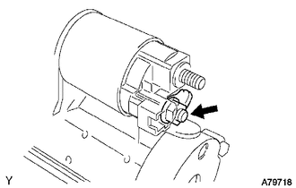
1. REMOVE MAGNETIC SWITCH ASSEMBLY
|
(a) Remove the nut and disconnect the lead wire from the magnetic switch. |
|
|
(b) Remove the 2 screws holding the magnetic switch to the starter drive housing. |
|
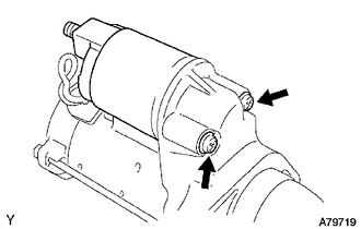
(c) Remove the magnetic switch.
(d) Remove the return spring and plunger from the starter drive housing.
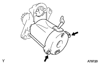
2. REMOVE STARTER YOKE ASSEMBLY
|
(a) Remove the 2 through-bolts, and pull out the starter yoke together with the commutator end frame. |
|
|
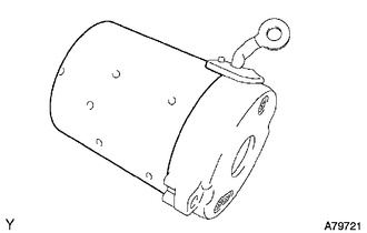
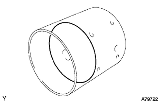
(b) Remove the starter yoke from the commutator end frame. |
|
3. REMOVE STARTER ARMATURE PLATE
|
(a) Remove the armature plate from the starter yoke. |
|
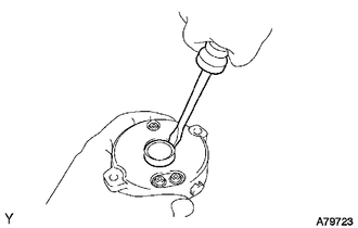
4. REMOVE STARTER COMMUTATOR END FRAME COVER
|
(a) Using a screwdriver, pry out the commutator end frame cover. |
|
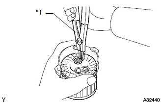
5. REMOVE STARTER ARMATURE ASSEMBLY
|
(a) Using snap ring pliers, remove the snap ring and plate washer. NOTICE: Do not drop the starter armature assembly. Text in Illustration
|
|
(b) Remove the armature from the commutator end frame.
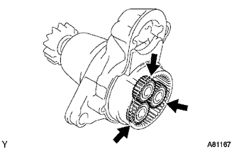
6. REMOVE PLANETARY GEAR
|
(a) Remove the 3 planetary gears from the starter drive housing. |
|
 Removal
REMOVAL
PROCEDURE
1. DISCONNECT CABLE FROM NEGATIVE BATTERY TERMINAL
NOTICE:
When disconnecting the cable, some systems need to be initialized after the cable
is reconnected (See page ).
2. RE ...
 Inspection
INSPECTION
PROCEDURE
1. INSPECT STARTER ASSEMBLY
NOTICE:
These tests must be performed within 3 to 5 seconds to avoid burning out the
coil.
(a) Perform a pull-in test.
(1) Remove the nut and d ...
Other materials about Toyota Venza:
USB Media Malfunction (B1585)
DESCRIPTION
This DTC is stored when a malfunction occurs in a connected device.
DTC No.
DTC Detection Condition
Trouble Area
B1585
When any of the following conditions is met:
A non m ...
Precaution
PRECAUTION
1. PRECAUTION FOR DISCONNECTING THE BATTERY CABLE
NOTICE:
When disconnecting the cable from the negative (-) battery terminal, initialize
the following systems after the terminal is reconnected.
System Name
See Procedure
...
Removal
REMOVAL
PROCEDURE
1. REMOVE BACK DOOR PANEL TRIM ASSEMBLY
2. REMOVE REAR WIPER ARM HEAD CAP
(a) Disengage the 4 claws and remove the rear wiper arm head cap as shown
in the illustration.
3. ...

0.1411