Toyota Venza: Installation
INSTALLATION
PROCEDURE
1. INSTALL FUEL INJECTOR ASSEMBLY
HINT:
Perform "Inspection After Repair" after replacing the fuel injector assembly
(See page .gif) ).
).
|
(a) Apply a light coat of gasoline or spindle oil to new O-rings, and then install one onto each fuel injector assembly. Text in Illustration
|
|
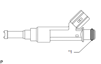
(b) Apply a light coat of gasoline or spindle oil to the contact surfaces of the new O-ring on each fuel injector assembly.
|
(c) While turning the fuel injector assembly left and right, install it onto the fuel delivery pipe sub-assembly. NOTICE: Make sure that the O-ring is not cracked or jammed when installing the
injector (See page |
|
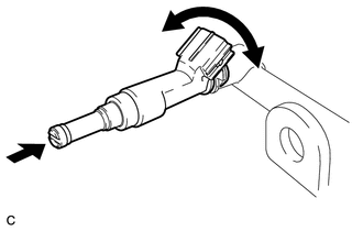
(d) Check that the fuel injector rotates smoothly. If the fuel injector does not rotate, replace the O-ring.
2. INSTALL FUEL DELIVERY PIPE SUB-ASSEMBLY
|
(a) Install 4 new injector vibration insulators to the cylinder head. Text in Illustration
|
|
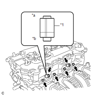
(b) Install the 2 fuel delivery spacers onto the cylinder head.
HINT:
Install the fuel delivery spacer so that the longer protrusion is on the cylinder head side.
(c) Install the fuel delivery pipe sub-assembly together with the 4 fuel injectors to the cylinder head, and then temporarily install the 2 bolts.
NOTICE:
Be careful not to drop the fuel injectors when installing the fuel delivery pipe sub-assembly.
(d) Tighten the 2 bolts to the specified torque.
Torque:
21 N·m {214 kgf·cm, 15 ft·lbf}
NOTICE:
- Do not drop the fuel injectors when installing the fuel delivery pipe sub-assembly.
- Check that the fuel injector assemblies rotate smoothly after installing the fuel delivery pipe sub-assembly.
3. CONNECT WIRE HARNESS
|
(a) Install the 2 wire harness brackets with the 2 bolts. Torque: 8.4 N·m {85 kgf·cm, 74 in·lbf} |
|
.png)
(b) Connect the 2 connectors.
(c) Connect the 4 fuel injector connectors.
(d) Engage the clamp to connect the wire harness.
4. INSTALL VACUUM SWITCHING VALVE ASSEMBLY (for ACIS)
5. CONNECT FUEL TUBE SUB-ASSEMBLY
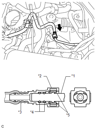
(a) Push the fuel tube connector to the fuel pipe until the fuel tube connector makes a "click" sound.
 Text in Illustration
|
*1 |
Fuel Pipe |
|
*2 |
Fuel Tube Connector |
|
*3 |
Nylon Tube |
|
*4 |
O-ring |
|
*5 |
Retainer |
.png) |
Push |
NOTICE:
- Before connecting the fuel tube connector and fuel pipe, check that there is no damage or foreign matter on the connecting part of the fuel pipe.
- After connecting the fuel tube connector and fuel pipe, check that they are securely connected by trying to pull them apart.
(b) Install the No. 1 fuel pipe clamp.
(c) Install the fuel tube sub-assembly to the fuel hose clamp.
6. INSTALL AIR CLEANER CAP SUB-ASSEMBLY
7. INSTALL NO. 1 VACUUM SWITCHING VALVE ASSEMBLY
8. INSTALL NO. 1 ENGINE COVER SUB-ASSEMBLY
9. INSTALL OUTER COWL TOP PANEL
10. INSTALL WINDSHIELD WIPER MOTOR AND LINK ASSEMBLY
(a) Install the windshield wiper motor and link assembly (See page
).
11. CONNECT CABLE TO NEGATIVE BATTERY TERMINAL
NOTICE:
When disconnecting the cable, some systems need to be initialized after the cable
is reconnected (See page ).
12. INSPECT FOR FUEL LEAK
 Inspection
INSPECTION
PROCEDURE
1. INSPECT FUEL INJECTOR ASSEMBLY
(a) Measure the resistance according to the value(s) in the table below.
Standard Resistance:
Tester Connec ...

Other materials about Toyota Venza:
Inspection
INSPECTION
PROCEDURE
1. INSPECT REAR POWER WINDOW REGULATOR MOTOR ASSEMBLY LH
(a) Apply positive (+) battery voltage to connector terminal 2 (B).
NOTICE:
Do not apply positive (+) battery voltage to any terminals other than
terminal 2 ( ...
Seat belts
Make sure that all occupants are wearing their seat belts before driving the
vehicle.
- Correct use of the seat belts
1. Extend the shoulder belt so that it comes fully over the shoulder, but does
not come into contact with the neck or slide off ...
Removal
REMOVAL
PROCEDURE
1. REMOVE FRONT WIPER ARM HEAD CAP
(a) Using a screwdriver, remove the 2 front wiper arm head caps as shown
in the illustration.
Text in Illustration
*1
Protective Tape
...

0.1584