Toyota Venza: Reassembly
REASSEMBLY
PROCEDURE
1. INSTALL NO. 1 CENTER SUPPORT BEARING ASSEMBLY
|
(a) Set the No. 1 center support bearing on the intermediate shaft as shown in the illustration. NOTICE: Make sure to install the bearing in the correct position. |
|
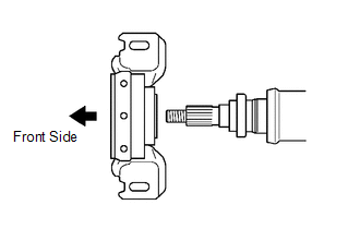
(b) Install a new washer to the intermediate shaft.
|
(c) Align the matchmarks on the universal joint flange and intermediate shaft and place the flange on the shaft. Text in Illustration
|
|
.png)
|
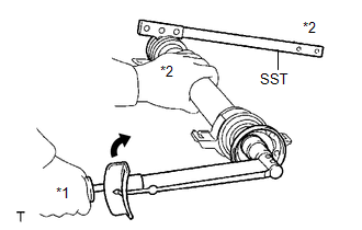
(d) Using SST to hold the universal joint flange, press the No. 1 center support bearing assembly into position by tightening a new nut and washer. SST: 09330-00021 Torque: 182 N·m {1851 kgf·cm, 134 ft·lbf} Text in Illustration
|
|
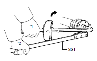
(e) Loosen the nut.
(f) Tighten the nut again.
Torque:
69 N·m {701 kgf·cm, 51 ft·lbf}
|
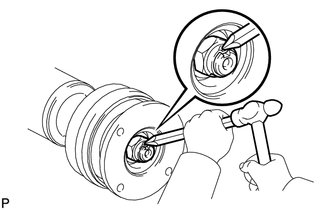
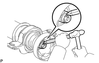
(g) Using a chisel and a hammer, stake the nut. |
|
2. INSTALL NO. 2 CENTER SUPPORT BEARING ASSEMBLY
|
(a) Set the No. 2 center support bearing on the intermediate shaft as shown in the illustration. NOTICE: Make sure to install the bearing in the correct position. |
|
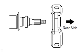
(b) Install a new washer to the intermediate shaft.
|
(c) Align the matchmarks on the universal joint flange and intermediate shaft, and place the flange on the shaft. Text in Illustration
|
|
.png)
|
(d) Using SST to hold the universal joint flange, press the No. 2 center support bearing assembly into position by tightening a new nut and washer. SST: 09330-00021 Torque: 182 N·m {1851 kgf·cm, 134 ft·lbf} Text in Illustration
|
|
(e) Loosen the nut.
(f) Tighten the nut again.
Torque:
69 N·m {701 kgf·cm, 51 ft·lbf}
|
(g) Using a chisel and a hammer, stake the nut. |
|
3. INSTALL INTERMEDIATE SHAFT
|
(a) Align the matchmarks on the intermediate shaft and rear propeller shaft, and then install 2 washers and 6 bolts. Text in Illustration
|
|
.png)
(b) Using a hexagon wrench (6 mm), tighten the 6 bolts with 2 washers temporarily.
4. INSTALL PROPELLER SHAFT
(a) Align the matchmarks on the propeller shaft and the universal joint flange.
|
(b) Install the propeller shaft to the front flange with the 4 bolts, 4 washers and 4 nuts. Torque: 74 N·m {750 kgf·cm, 55 ft·lbf} NOTICE:
|
|
.png)
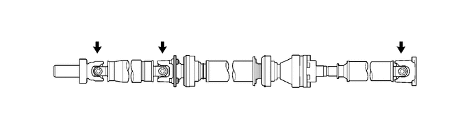
(c) Check that each joint of the propeller with center bearing shaft assembly is facing the direction shown in the illustration.
 Installation
INSTALLATION
PROCEDURE
1. TEMPORARILY TIGHTEN PROPELLER WITH CENTER BEARING SHAFT ASSEMBLY
(a) Remove SST from the transfer.
SST: 09325-20010
...
 Propeller Shaft System
Problem Symptoms Table
PROBLEM SYMPTOMS TABLE
HINT:
Use the table below to help determine the cause of problem symptoms. If multiple
suspected areas are listed, the potential causes of the symp ...
Other materials about Toyota Venza:
Using a flat bed truck
If you use chains or cables to tie down your vehicle, the angles shaded in black
must be 45°.
Do not overly tighten the tie downs or the vehicle may be damaged.
NOTICE
- To prevent body damage when towing a sling-type truck
Do not tow with a sli ...
Customize Parameters
CUSTOMIZE PARAMETERS
1. CUSTOMIZING FUNCTION WITH THE TECHSTREAM
HINT:
The following items can be customized.
NOTICE:
When the customer requests a change in a function, first make sure that
the function can be customized.
Be sure to make a ...
Coolant Thermostat (Coolant Temperature Below Thermostat Regulating Temperature)
(P0128)
DESCRIPTION
HINT:
This DTC relates to the thermostat.
This DTC is stored when the engine coolant temperature does not reach 75°C (167°F)
despite sufficient engine warm-up time having elapsed.
DTC No.
DTC Detection Condition
...

0.1555