Toyota Venza: Reassembly
REASSEMBLY
CAUTION / NOTICE / HINT
HINT:
Use an overhaul stand as necessary.
PROCEDURE
1. INSTALL DIFFERENTIAL RING GEAR
(a) Clean the contact surfaces of the rear differential case sub-assembly and differential ring gear.
(b) Heat the differential ring gear in boiling water.
(c) Carefully remove the differential ring gear from the boiling water.
CAUTION:
Do not burn yourself.
|
(d) Secure the rear differential case sub-assembly between aluminum plates in a vise. Text in Illustration
NOTICE: Do not overtighten the vise. |
|
.png)
(e) After the moisture on the differential ring gear has completely evaporated, quickly install the differential ring gear to the rear differential case sub-assembly.
(f) Align the matchmarks on the rear differential case sub-assembly and differential ring gear, and install the differential ring gear.
(g) Temporarily install 12 new rear differential case bolts to which thread lock has been applied.
Adhesive:
Toyota Genuine Adhesive 1360K, Three Bond 1360K or equivalent.
(h) After the ring gear has cooled sufficiently, tighten the 12 new rear differential case bolts.
Torque:
99 N·m {1005 kgf·cm, 73 ft·lbf}
NOTICE:
- New rear differential case bolts should be used every time the differential ring gear is installed.
- Install the new rear differential case bolts by tightening diametrically opposite bolts uniformly in several passes.
- Tighten the rear differential case bolts after the differential ring gear has cooled down sufficiently.
- Do not allow any oil to contact the rear differential case bolt, differential ring gear threads or rear differential case sub-assembly seating surface.
2. INSTALL REAR DIFFERENTIAL CASE BEARING (for LH Side)
NOTICE:
New bearings are coated with anti-rust oil. If using new bearings, do not wash it off.
HINT:
Perform this step only when replacing the rear differential case bearing or rear differential case sub-assembly.
|
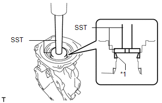
(a) Using SST and a press, install a new rear differential case bearing (LH side inner race) to the rear differential case sub-assembly. SST: 09223-46011 NOTICE: Replace the inner and outer races as a set. |
|
3. INSTALL REAR DIFFERENTIAL CASE BEARING (for RH Side)
NOTICE:
New bearings are coated with anti-rust oil. If using new bearings, do not wash it off.
HINT:
Perform this step only when replacing the rear differential case bearing or rear differential case sub-assembly.
|
(a) Using SST and a press, install the rear differential case bearing (RH side inner race) to the rear differential case sub-assembly. SST: 09223-46011 NOTICE: Replace the inner and outer races as a set. |
|
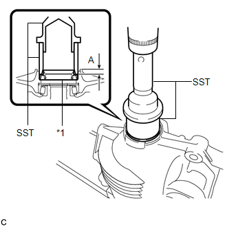
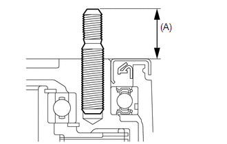
4. INSTALL STRAIGHT PIN
(a) Using a plastic hammer, install the 4 straight pins to the rear differential carrier.
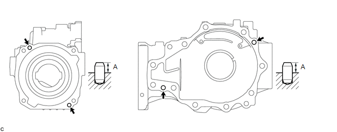
Protrusion (A):
8 to 9 mm (0.315 to 0.354 in.)
5. INSTALL REAR DRIVE PINION REAR TAPERED ROLLER BEARING
NOTICE:
New bearings are coated with anti-rust oil. If using new bearings, do not wash it off.
|
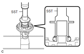
(a) Using SST, bolt, nuts and washers, install the rear drive pinion rear tapered roller bearing (outer race) to the rear differential carrier. SST: 09950-60010 09951-00500 09951-00530 SST: 09950-60020 09951-00680 09951-00890 Text in Illustration
HINT: Use M12 x P1.5 bolts with shaft lengths of 124 mm (4.88 in.) and M12 x P1.5 nuts for installation. |
|
6. INSTALL REAR DRIVE PINION FRONT TAPERED ROLLER BEARING
NOTICE:
New bearings are coated with anti-rust oil. If using new bearings, do not wash it off.
|
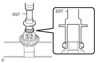
(a) Using SST and a press, install the rear drive pinion front tapered roller bearing (outer race) to the rear differential carrier. SST: 09950-60010 09951-00610 SST: 09950-70010 09951-07150 Text in Illustration
|
|
7. INSTALL REAR DRIVE PINION REAR TAPERED ROLLER BEARING
NOTICE:
New bearings are coated with anti-rust oil. If using new bearings, do not wash it off.
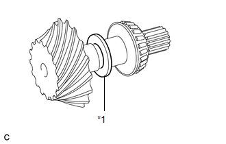
(a) Install the rear differential drive pinion plate washer to the differential drive pinion.
NOTICE:
Install each rear differential drive pinion plate washer to the position it was removed from.
|
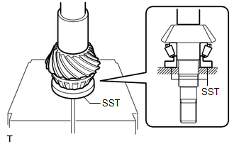
(b) Using SST and a press, install the rear drive pinion rear tapered roller bearing (inner race) to the differential drive pinion. SST: 09506-30012 |
|
8. INSTALL REAR DIFFERENTIAL CASE BEARING (for LH Side)
NOTICE:
New bearings are coated with anti-rust oil. If using new bearings, do not wash it off.
HINT:
Replace the rear differential case bearing (LH side outer race) when removing the rear differential case bearing (LH side inner race) from the rear differential case sub-assembly.
|
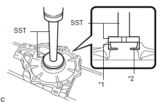
(a) Using SST and a press, install the rear differential side gear shaft plate washer and a new rear differential case bearing (LH side outer race) to the differential side bearing retainer. SST: 09950-60020 09951-00680 SST: 09950-70010 09951-07150 Text in Illustration
NOTICE:
|
|
9. INSTALL REAR DIFFERENTIAL CASE BEARING (for RH Side)
NOTICE:
New bearings are coated with anti-rust oil. If using new bearings, do not wash it off.
|
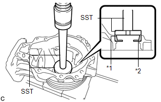
(a) Using SST and a press, install the rear differential side gear shaft plate washer and the rear differential case bearing (RH side outer race) to the rear differential carrier. SST: 09950-60020 09951-00680 SST: 09950-70010 09951-07150 Text in Illustration
NOTICE:
|
|
10. ADJUST DIFFERENTIAL DRIVE PINION PRELOAD
|
(a) Install the differential drive pinion with rear drive pinion rear tapered roller bearing (inner race) to the rear differential carrier. |
|
.png)
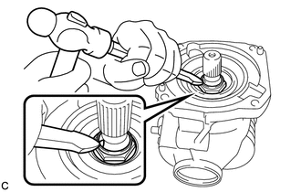
(b) Apply hypoid gear oil LSD to the threads of a new rear drive pinion nut and its seating surface.
(c) Install the rear drive pinion front tapered roller bearing (inner race) and rear drive pinion nut to the differential drive pinion.
NOTICE:
New bearings are coated with anti-rust oil. If using new bearings, do not wash it off.
|
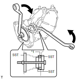
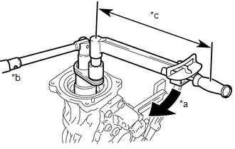
(d) Using SST, gradually tighten the rear drive pinion nut until the specified preload is reached. Do not exceed the torque limit shown below. SST: 09556-16011 SST: 09564-16020 Text in Illustration
Torque: Specified tightening torque : 321 N·m {3273 kgf·cm, 237 ft·lbf} or less NOTICE:
|
|
.gif) ).
). 
|
(e) Using SST and a torque wrench, measure the preload (starting torque) of the differential drive pinion. SST: 09556-16011 Standard Drive Pinion Preload (Starting Torque)
HINT: For a more accurate measurement, rotate the bearing forward and backward before inspection. |
|
.png)
11. INSTALL REAR DIFFERENTIAL CASE ASSEMBLY
(a) Using a scraper and wire brush, remove the seal packing from the rear differential carrier and differential side bearing retainer.
NOTICE:
- Do not damage the contact surface.
- Be sure to completely remove all seal packing from the rear differential carrier and differential side bearing retainer.
- Do not allow the removed seal packing to enter the rear differential carrier.
|
(b) Install the rear differential case assembly to the rear differential carrier. |
|
.png)
|
(c) Install the differential side bearing retainer to the rear differential carrier with the 10 bolts. Torque: 42 N·m {430 kgf·cm, 31 ft·lbf} |
|
.png)
12. INSPECT DIFFERENTIAL RING GEAR BACKLASH
|
(a) Insert a dial indicator and magnetic base through the rear differential filler plug hole, and set it perpendicular to a differential ring gear tooth tip. |
|
.png)
(b) Using SST, hold the differential drive pinion in place.
SST: 09556-16011
(c) Using SST, rotate the rear differential case assembly forward and backward, and measure the backlash.
SST: 09564-32011
Backlash:
0.13 to 0.25 mm (0.00512 to 0.00984 in.)
HINT:
Measure at 3 or more areas on the circumference of the differential ring gear.
(d) If the result is not within the specified range, select rear differential side gear shaft plate washers that are thicker or thinner as necessary. Adjust the thickness of the left and right rear differential side gear shaft plate washers in equal increments. Then install the rear differential case bearing (outer race).
HINT:
- Adjust the thickness of the LH and RH rear differential side gear shaft plate washers by the same amount each time until the backlash is within the standard range. If the thickness on the LH side is increased, decrease the thickness on the RH side, and if the thickness on the LH side is decreased, increase the thickness on the RH side.
- When the backlash is smaller than the specified value, select a thick rear differential side gear shaft plate washer for the RH side and thin rear differential side gear shaft plate washer for the LH side.
- When the backlash is larger than the specified value, select a thin rear differential side gear shaft plate washer for the RH side and thick rear differential side gear shaft plate washer for the LH side.
|
Mark |
Thickness mm (in.) |
Mark |
Thickness mm (in.) |
|---|---|---|---|
|
75 |
1.74 to 1.76 (0.0686 to 0.0692) |
96 |
2.34 to 2.36 (0.0922 to 0.0929) |
|
76 |
1.77 to 1.79 (0.0697 to 0.0704) |
97 |
2.37 to 2.39 (0.0934 to 0.0940) |
|
77 |
1.80 to 1.82 (0.0709 to 0.0716) |
98 |
2.40 to 2.42 (0.0945 to 0.0952) |
|
78 |
1.83 to 1.85 (0.0721 to 0.0728) |
99 |
2.43 to 2.45 (0.0957 to 0.0964) |
|
79 |
1.86 to 1.88 (0.0733 to 0.0740) |
00 |
2.46 to 2.48 (0.0969 to 0.0976) |
|
80 |
1.89 to 1.91 (0.0745 to 0.0751) |
01 |
2.49 to 2.51 (0.0981 to 0.0988) |
|
81 |
1.92 to 1.94 (0.0756 to 0.0763) |
02 |
2.52 to 2.54 (0.0993 to 0.0999) |
|
82 |
1.95 to 1.97 (0.0768 to 0.0775) |
03 |
2.55 to 2.57 (0.1004 to 0.1011) |
|
83 |
1.98 to 2.00 (0.0780 to 0.0787) |
04 |
2.58 to 2.60 (0.1016 to 0.1023) |
|
84 |
2.01 to 2.03 (0.0792 to 0.0799) |
05 |
2.61 to 2.63 (0.1028 to 0.1035) |
|
85 |
2.04 to 2.06 (0.0804 to 0.0811) |
06 |
2.64 to 2.66 (0.1040 to 0.1047) |
|
86 |
2.07 to 2.09 (0.0815 to 0.0822) |
07 |
2.67 to 2.69 (0.1052 to 0.1059) |
|
88 |
2.10 to 2.12 (0.0827 to 0.0834) |
08 |
2.70 to 2.72 (0.1063 to 0.1070) |
|
89 |
2.13 to 2.15 (0.0839 to 0.0846) |
09 |
2.73 to 2.75 (0.1075 to 0.1082) |
|
90 |
2.16 to 2.18 (0.0851 to 0.0858) |
10 |
2.76 to 2.78 (0.1087 to 0.1094) |
|
91 |
2.19 to 2.21 (0.0863 to 0.0870) |
11 |
2.79 to 2.81 (0.1099 to 0.1106) |
|
92 |
2.22 to 2.24 (0.0875 to 0.0881) |
12 |
2.82 to 2.84 (0.1111 to 0.1118) |
|
93 |
2.25 to 2.27 (0.0886 to 0.0893) |
13 |
2.85 to 2.87 (0.1123 to 0.1129) |
|
94 |
2.28 to 2.30 (0.0898 to 0.0905) |
14 |
2.88 to 2.90 (0.1134 to 0.1141) |
|
95 |
2.31 to 2.33 (0.0910 to 0.0917) |
- |
- |
13. ADJUST TOOTH CONTACT BETWEEN RING GEAR AND DRIVE PINION
(a) Remove the 10 bolts and the differential side bearing retainer.
(b) Remove the rear differential case assembly from the rear differential carrier.
(c) Coat 3 or 4 teeth at 4 different positions on the differential ring gear with Prussian blue.
(d) Install the rear differential case assembly to the rear differential carrier.
|
(e) Install the differential side bearing retainer with the 10 bolts. Torque: 42 N·m {430 kgf·cm, 31 ft·lbf} |
|
(f) Turn the differential drive pinion at least 10 times.
(g) Remove the 10 bolts and the differential side bearing retainer.
(h) Remove the rear differential case assembly from the rear differential carrier.
(i) Inspect the tooth contact pattern.
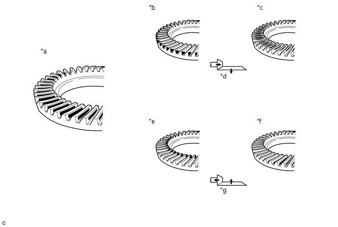 Text in Illustration
|
*a |
Proper Contact |
*b |
Heel Contact |
|
*c |
Face Contact |
*d |
Select washers that will bring the drive pinion closer to the ring gear |
|
*e |
Toe Contact |
*f |
Flank Contact |
|
*g |
Select washers that will bring the drive pinion away from the ring gear |
- |
- |
HINT:
Check the tooth contact pattern at 2 or more positions on the circumference of the differential ring gear.
(j) Perform the following procedure for face or flank contact:
(1) If the result is not within the specified range, select rear differential side gear shaft plate washers that are thicker or thinner as necessary. Adjust the thickness of the left and right rear differential side gear shaft plate washers in equal increments. Then install the rear differential case bearing (outer race).
(2) Repeat the differential ring gear and differential drive pinion tooth contact pattern inspection.
HINT:
If the tooth contact pattern is not correct, reselect rear differential side gear shaft plate washers and reinspect the tooth contact pattern.
(3) Repeat the differential ring gear and differential drive pinion backlash inspection.
HINT:
If the differential ring gear and differential drive pinion backlash are not as specified, reselect the rear differential drive pinion plate washer and then readjust the differential drive pinion preload, differential ring gear and differential drive pinion backlash and reinspect the tooth contact pattern.
(k) Perform the following procedure for heel or toe contact:
|
(1) Select a rear differential drive pinion plate washer again and install the rear drive pinion rear tapered roller bearing (inner race). Text in Illustration
|
|
(l) Readjust the differential drive pinion preload, differential ring gear and differential drive pinion backlash and reinspect the tooth contact pattern.
14. INSPECT TOTAL PRELOAD
|
(a) Using SST and a torque wrench, measure the total preload (starting torque) with the teeth of the differential drive pinion and differential ring gear in contact. SST: 09556-16011 Standard Total Preload (Starting Torque)
HINT: For a more accurate measurement, rotate the rear differential case bearing forward and backward before measuring. |
|
(b) If the results are not within the specification, perform the procedure below:
(1) Select a thicker or thinner rear differential side gear shaft plate washer for the RH side, and then install the rear differential case bearing outer race (RH side only).
(2) Repeat the total preload measurement.
(3) Repeat the differential ring gear and differential drive pinion backlash inspection.
(4) Repeat the differential ring gear and differential drive pinion tooth contact pattern inspection.
15. REMOVE DIFFERENTIAL SIDE BEARING RETAINER
|
(a) Remove the 10 bolts and differential side bearing retainer. |
|
16. REMOVE REAR DIFFERENTIAL CASE ASSEMBLY
|
(a) Remove the rear differential case assembly from the rear differential carrier. |
|
17. REMOVE DIFFERENTIAL DRIVE PINION
|
(a) Remove the differential drive pinion from the rear differential carrier. |
|
18. INSTALL REAR DIFFERENTIAL DRIVE PINION BEARING SPACER
|
(a) Install a new rear differential drive pinion bearing spacer to the differential drive pinion. HINT: Face the smaller inside diameter towards the front of the vehicle. |
|
.png)
19. INSTALL REAR DIFFERENTIAL DRIVE PINION OIL SLINGER
|
(a) Install the rear differential drive pinion oil slinger to the differential drive pinion. |
|
.png)
20. INSTALL DIFFERENTIAL DRIVE PINION
|
(a) Install the differential drive pinion to the rear differential carrier. |
|
|
(b) Install the differential side bearing retainer with the 10 bolts. Torque: 42 N·m {430 kgf·cm, 31 ft·lbf} |
|
21. TEMPORARILY TIGHTEN REAR DRIVE PINION NUT
(a) Apply hypoid gear oil LSD to the threads of the rear drive pinion nut and its seating surface.
|
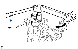
(b) Using SST, temporarily install the rear drive pinion nut to the differential drive pinion. SST: 09556-16011 SST: 09564-16020 Text in Illustration
|
|
|
(c) Using SST and a torque wrench, inspect the differential drive pinion preload (starting torque). SST: 09556-16011 Standard Drive Pinion Preload (Starting Torque)
HINT: For a more accurate measurement, rotate the bearing forward and backward before adjustment. |
|
|
(d) If the preload is insufficient, use SST to tighten the rear drive pinion nut 5° to 10° at a time. Measure the drive pinion preload and repeat the adjustment as necessary until the preload matches the specified torque. SST: 09556-16011 SST: 09564-16020 Text in Illustration
Torque: Specified tightening torque : 321 N·m {3273 kgf·cm, 237 ft·lbf} or less NOTICE:
|
|
(e) If the tightening torque of the rear drive pinion nut exceeds the specified torque but the preload is still insufficient, remove the rear drive pinion nut. Then check if the rear drive pinion nut and differential drive pinion screw threads are damaged.
(f) If no damage is found, replace the rear differential drive pinion bearing spacer, apply hypoid gear oil LSD to rear drive pinion nut threads and repeat the procedure above.
22. REMOVE DIFFERENTIAL SIDE BEARING RETAINER
|
(a) Remove the 10 bolts and differential side bearing retainer. |
|
23. INSTALL REAR DIFFERENTIAL BREATHER PLUG OIL DEFLECTOR
|
(a) Install the rear differential breather plug oil deflector with the 2 bolts. Torque: 6.5 N·m {66 kgf·cm, 58 in·lbf} |
|
.png)
24. INSTALL REAR DIFFERENTIAL CASE ASSEMBLY
|
(a) Install the rear differential case assembly to the rear differential carrier. |
|
25. INSTALL DIFFERENTIAL SIDE BEARING RETAINER
|
(a) Install the differential side bearing retainer to the rear differential carrier with the 10 bolts. Torque: 42 N·m {430 kgf·cm, 31 ft·lbf} |
|
26. INSPECT DIFFERENTIAL RING GEAR BACKLASH
|
(a) Insert a dial indicator and magnetic base through the rear differential filler plug hole, and set it perpendicular to a differential ring gear tooth tip. |
|
(b) Using SST, hold the differential drive pinion in place.
SST: 09556-16011
(c) Using SST, rotate the rear differential case assembly forward and backward, and measure the backlash.
SST: 09564-32011
Backlash:
0.13 to 0.25 mm (0.00512 to 0.00984 in.)
If the backlash is not within the specification, adjust the side bearing preload or repair as necessary.
HINT:
Measure at 3 or more areas on the circumference of the differential ring gear.
27. INSPECT TOTAL PRELOAD
|
(a) Using SST and a torque wrench, measure the total preload (starting torque) with the teeth of the differential drive pinion and differential ring gear in contact. SST: 09556-16011 Standard Total Preload (Starting Torque)
HINT: For a more accurate measurement, rotate the rear differential case bearing forward and backward before measuring. |
|
(b) If the results are not within the specification, perform the procedure below:
(1) Select a thicker or thinner rear differential side gear shaft plate washer for the RH side, and then install the rear differential case bearing outer race (RH side only).
(2) Repeat the total preload measurement.
(3) Repeat the differential ring gear and differential drive pinion backlash inspection.
(4) Repeat the differential ring gear and differential drive pinion tooth contact pattern inspection.
28. INSTALL DIFFERENTIAL SIDE BEARING RETAINER
|
(a) Remove the 10 bolts and differential side bearing retainer. |
|
(b) Using a non-residue solvent, remove grease and oil from the contact surfaces of the rear differential carrier and differential side bearing retainer.
NOTICE:
Do not damage the contact surface.
|
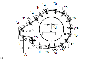
(c) Apply seal packing to the areas indicated in the illustration of the rear differential carrier. Text in Illustration
Seal packing: Toyota Genuine Seal Packing 1281, Three Bond 1281 or equivalent NOTICE:
|
|
|
(d) Install the differential side bearing retainer to the rear differential carrier with the 10 bolts. Torque: 42 N·m {430 kgf·cm, 31 ft·lbf} NOTICE: After installing the differential side bearing retainer, do not add oil or drive the vehicle for at least 1 hour. In addition, avoid sudden acceleration and deceleration for a minimum of 12 hours. |
|
29. INSPECT TOTAL PRELOAD
|
(a) Using SST and a torque wrench, measure the total preload (starting torque) with the teeth of the differential drive pinion and differential ring gear in contact. SST: 09556-16011 Standard Total Preload (Starting Torque)
HINT: For a more accurate measurement, rotate the rear differential case bearing forward and backward before measuring. |
|
30. INSPECT DIFFERENTIAL RING GEAR BACKLASH
|
(a) Insert a dial indicator and magnetic base through the rear differential filler plug hole, and set it perpendicular to a differential ring gear tooth tip. |
|
(b) Using SST, hold the differential drive pinion in place.
SST: 09556-16011
(c) Using SST, rotate the rear differential case assembly forward and backward, and measure the backlash.
SST: 09564-32011
Backlash:
0.13 to 0.25 mm (0.00512 to 0.00984 in.)
If the backlash is not within the specification, adjust the side bearing preload or repair as necessary.
HINT:
Measure at 3 or more areas on the circumference of the differential ring gear.
31. INSTALL REAR DRIVE PINION NUT
|
(a) Using a chisel and a hammer, stake the rear drive pinion nut as shown in the illustration. |
|
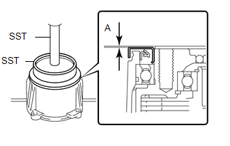
32. INSTALL DIAPHRAGM OIL SEAL
|
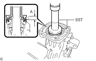
(a) Using SST and a press, install a new diaphragm oil seal into the rear differential carrier assembly. SST: 09506-35010 SST: 09554-22010 Text in Illustration
Standard Distance (A): 0.7 to 1.3 mm (0.0276 to 0.0511 in.) NOTICE:
|
|
33. INSTALL REAR DIFFERENTIAL SIDE GEAR SHAFT OIL SEAL (for LH Side)
|
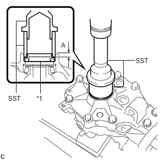
(a) Using SST and a press, install a new rear differential side gear shaft oil seal into the differential side bearing retainer. SST: 09223-46011 SST: 09631-32020 Text in Illustration
Standard Distance (A): 8.2 to 8.8 mm (0.323 to 0.346 in.) NOTICE:
|
|
34. INSTALL REAR DIFFERENTIAL SIDE GEAR SHAFT OIL SEAL (for RH Side)
|
(a) Using SST and a press, install a new rear differential side gear shaft oil seal into the rear differential carrier. SST: 09223-46011 SST: 09631-32020 Text in Illustration
Standard Distance (A): 8.2 to 8.8 mm (0.323 to 0.346 in.) NOTICE:
|
|
35. INSTALL CONNECTOR CLAMP BRACKET
|
(a) Install the connector clamp bracket with the bolt. Torque: 15 N·m {150 kgf·cm, 11 ft·lbf} |
|
.png)
(b) Engage the claw to install the electro magnetic control coupling wire harness connector.
NOTICE:
Do not damage the electro magnetic control coupling wire harness.
36. INSTALL TRANSMISSION COUPLING SPACER
|
(a) Install the transmission coupling spacer to the rear differential carrier assembly. Text in Illustration
NOTICE: Keep the transmission coupling spacer free of oil and foreign matter. |
|
.png)
37. INSTALL TRANSMISSION COUPLING CONICAL SPRING WASHER
|
(a) Install the transmission coupling conical spring washer to the rear differential carrier assembly as shown in the illustration. Text in Illustration
NOTICE: Keep the transmission coupling conical spring washer free of oil and foreign matter. |
|
.png)
38. INSTALL REAR DIFFERENTIAL DUST DEFLECTOR
|
(a) Align the matchmarks on the rear differential dust deflector and electro magnetic control coupling sub-assembly, and temporarily install the rear differential dust deflector. Text in Illustration
|
|
|
(b) Using SST and a press, install the rear differential dust deflector. SST: 09223-15030 SST: 09950-70010 09951-07150 Standard Distance (A): 0 to 0.6 mm (0 to 0.0236 in.) NOTICE: Do not damage the end surface of the electro magnetic control coupling sub-assembly. HINT: If the end surface of the electro magnetic control coupling sub-assembly is damaged while installing the rear differential dust deflector, replace the electro magnetic control coupling sub-assembly with a new one. |
|
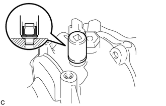
39. INSTALL STUD BOLT
(a) Temporarily install 4 new stud bolts to the electro magnetic control coupling sub-assembly.
|
(b) Install 2 service nuts to the stud bolt. Text in Illustration
Recommended Service Nut: Thread Diameter 8.0 mm (0.315 in.) Thread Pitch 1.25 mm (0.0492 in.) |
|
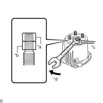
(c) Lock the upper nut using the lower nut.
|
(d) Turn the upper nut and tighten the other 3 stud bolts to the electro magnetic control coupling sub-assembly in the same way. Torque: 9.8 N·m {100 kgf·cm, 87 in·lbf} Standard Distance (A): 29.1 to 32.4 mm (1.15 to 1.27 in.) NOTICE: Prevent foreign matter from entering the electro magnetic control coupling sub-assembly. HINT: If the threads of the electro magnetic control coupling sub-assembly are damaged while installing the stud bolt, replace the electro magnetic control coupling sub-assembly with a new one. |
|
40. INSTALL ELECTRO MAGNETIC CONTROL COUPLING SUB-ASSEMBLY
(a) Using a scraper and wire brush, remove the seal packing from the rear differential carrier assembly and electro magnetic control coupling sub-assembly.
NOTICE:
- Do not damage the contact surface.
- Be sure to completely remove all seal packing from the rear differential carrier assembly and electro magnetic control coupling sub-assembly.
- Do not allow the removed seal packing to enter the rear differential carrier assembly and electro magnetic control coupling sub-assembly.
(b) Using a non-residue solvent, remove grease and oil from the contact surfaces of the rear differential carrier assembly and the electro magnetic control coupling sub-assembly.
NOTICE:
Do not damage the contact surface.
|
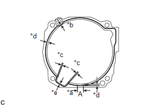
(c) Apply seal packing to the areas indicated in the illustration of the rear differential carrier assembly. Text in Illustration
Seal packing: Toyota Genuine Seal Packing 1281, Three Bond 1281 or equivalent NOTICE:
|
|
|
(d) Install the electro magnetic control coupling sub-assembly with the 4 bolts. Torque: 20 N·m {200 kgf·cm, 14 ft·lbf} NOTICE:
|
|
.png)
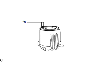
41. INSTALL REAR DIFFERENTIAL CARRIER COVER BREATHER PLUG
|
(a) Using a socket wrench, service nut and a hammer, install a new rear differential carrier cover breather plug to the rear differential carrier. NOTICE: Tap the rear differential carrier cover breather plug in until the flange meets the edge of the rear differential carrier. HINT:
|
|
42. INSPECT RUNOUT OF ELECTRO MAGNETIC CONTROL COUPLING SUB-ASSEMBLY
|
(a) Install a dial indicator and magnetic base perpendicular to the inner side of the electro magnetic control coupling sub-assembly as shown in the illustration. |
|
.png)
(b) Using SST, rotate the electro magnetic control coupling sub-assembly forward and backward, and measure the vertical runout.
SST: 09564-32011
Maximum Runout:
0.06 mm (0.00236 in.)
If the runout is greater than the maximum value, replace the electro magnetic control coupling sub-assembly.
(c) Install a dial indicator and magnetic base perpendicular to the electro magnetic control coupling sub-assembly as shown in the illustration.
(d) Using SST, rotate the electro magnetic control coupling sub-assembly forward and backward, and measure the lateral runout.
SST: 09564-32011
Maximum Runout:
0.07 mm (0.00276 in.)
If the runout is greater than the maximum value, replace the electro magnetic control coupling sub-assembly.
43. INSTALL REAR DIFFERENTIAL FILLER PLUG
|
(a) Install a new gasket and the rear differential filler plug. Torque: 49 N·m {500 kgf·cm, 36 ft·lbf} |
|
.png)
 Disassembly
DISASSEMBLY
CAUTION / NOTICE / HINT
HINT:
Use an overhaul stand as necessary.
PROCEDURE
1. REMOVE REAR DIFFERENTIAL FILLER PLUG
(a) Remove the rear differential filler plug and gasket ...
 Installation
INSTALLATION
CAUTION / NOTICE / HINT
NOTICE:
If installing a new rear differential carrier assembly, remove the 2 differential
side seal caps before installing the rear drive shaft assembly.
PRO ...
Other materials about Toyota Venza:
Child Restraint Seat Tether Anchor
Components
COMPONENTS
ILLUSTRATION
Installation
INSTALLATION
PROCEDURE
1. INSTALL CHILD RESTRAINT SEAT TETHER ANCHOR BRACKET
(a) Engage the guide.
(b) Install the child restraint seat teth ...
Brake Switch "A" Circuit (P0571)
DESCRIPTION
When the brake pedal is depressed, the stop light switch assembly sends a signal
to the ECM. When the ECM receives this signal, it cancels the cruise control. The
fail-safe function operates to enable normal driving even if there is a malfunct ...
Occupant Classification Sensor Power Supply Circuit Malfunction (B1793)
DESCRIPTION
The occupant classification sensor power supply circuit consists of the occupant
classification ECU and occupant classification sensors.
DTC B1793 is recorded when a malfunction is detected in the occupant classification
sensor power supply c ...

0.1271