Toyota Venza: Brake Switch "A" Circuit (P0571)
DESCRIPTION
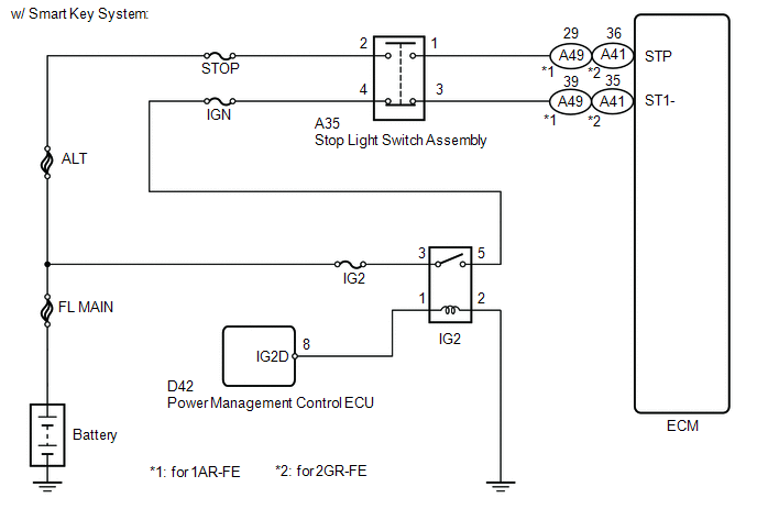
When the brake pedal is depressed, the stop light switch assembly sends a signal to the ECM. When the ECM receives this signal, it cancels the cruise control. The fail-safe function operates to enable normal driving even if there is a malfunction in the stop light signal circuit. Cruise control cancellation occurs when voltage is applied to terminal STP. When the brake is applied, voltage is normally applied to terminal STP of the ECM through the STOP fuse and the stop light switch assembly, and the ECM turns the cruise control off.
|
DTC |
DTC Detection Condition |
Trouble Area |
|---|---|---|
|
P0571 |
Voltage of STP signal and that of ST1- signal of ECM are less than 1 V for 0.5 seconds or more |
|
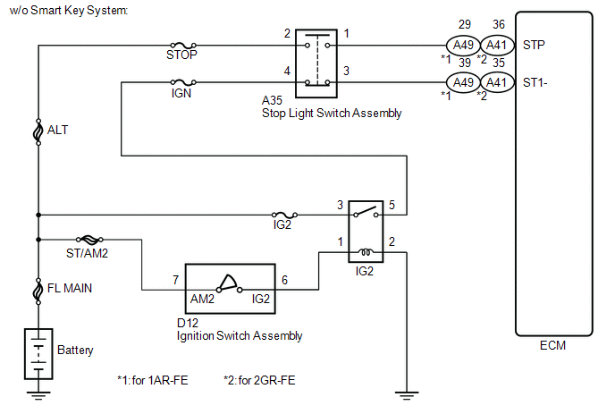
WIRING DIAGRAM
CAUTION / NOTICE / HINT
HINT:
Inspect the fuses for circuits related to this system before performing the following inspection procedure.
PROCEDURE
|
1. |
INSPECT STOP LIGHT SWITCH ASSEMBLY (POWER SOURCE) |
|
(a) Disconnect the stop light switch assembly connector. |
|
(b) Measure the voltage according to the value(s) in the table below.
Standard Voltage:
|
Tester Connection |
Condition |
Specified Condition |
|---|---|---|
|
A35-2 - Body ground |
Always |
11 to 14 V |
|
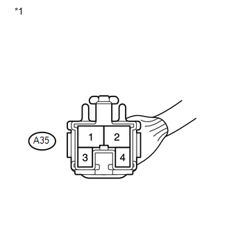
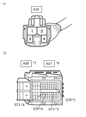
*1 |
Front view of wire harness connector (to Stop Light Switch Assembly) |
(c) Reconnect the stop light switch assembly connector.
| NG | .gif) |
REPAIR OR REPLACE HARNESS OR CONNECTOR (STOP LIGHT SWITCH ASSEMBLY - BATTERY) |
|
.gif)
|
2. |
INSPECT STOP LIGHT SWITCH ASSEMBLY (POWER SOURCE) |
|
(a) Disconnect the stop light switch assembly connector. |
|
(b) Turn the ignition switch to ON.
(c) Measure the voltage according to the value(s) in the table below.
Standard Voltage:
|
Tester Connection |
Switch Condition |
Specified Condition |
|---|---|---|
|
A35-4 - Body ground |
Ignition switch ON |
11 to 14 V |
|
*1 |
Front view of wire harness connector (to Stop Light Switch Assembly) |
(d) Reconnect the stop light switch assembly connector.
| NG | |
REPAIR OR REPLACE HARNESS OR CONNECTOR (STOP LIGHT SWITCH ASSEMBLY - IGN FUSE) |
|
|
3. |
INSPECT STOP LIGHT SWITCH ASSEMBLY |
|
(a) Remove the stop light switch assembly (See page
|
|
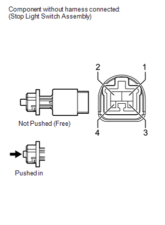
(b) Measure the resistance according to the value(s) in the table below.
Standard Resistance:
|
Tester Connection |
Switch Condition |
Specified Condition |
|---|---|---|
|
1 - 2 |
Switch pin not pushed |
Below 1 Ω |
|
3 - 4 |
Switch pin not pushed |
10 kΩ or higher |
|
1 - 2 |
Switch pin pushed |
10 kΩ or higher |
|
3 - 4 |
Switch pin pushed |
Below 1 Ω |
(c) Reinstall the stop light switch assembly (See page
.gif) ).
).
| NG | |
REPLACE STOP LIGHT SWITCH ASSEMBLY |
|
|
4. |
CHECK HARNESS AND CONNECTOR (ECM - STOP LIGHT SWITCH ASSEMBLY) |
|
(a) Disconnect the ECM connector. |
|
(b) Disconnect the stop light switch assembly connector.
(c) Measure the resistance according to the value(s) in the table below.
Standard Resistance (Check for Open):
For 1AR-FE|
Tester Connection |
Condition |
Specified Condition |
|---|---|---|
|
A49-29 (STP) - A35-1 |
Always |
Below 1 Ω |
|
A49-39 (ST1-) - A35-3 |
Always |
Below 1 Ω |
|
Tester Connection |
Condition |
Specified Condition |
|---|---|---|
|
A41-36 (STP) - A35-1 |
Always |
Below 1 Ω |
|
A41-35 (ST1-) - A35-3 |
Always |
Below 1 Ω |
Standard Resistance (Check for Short):
For 1AR-FE|
Tester Connection |
Condition |
Specified Condition |
|---|---|---|
|
A49-29 (STP) or A35-1 - Body ground |
Always |
10 kΩ or higher |
|
A49-39 (ST1-) or A35-3 - Body ground |
Always |
10 kΩ or higher |
|
Tester Connection |
Condition |
Specified Condition |
|---|---|---|
|
A41-36 (STP) or A35-1 - Body ground |
Always |
10 kΩ or higher |
|
A41-35 (ST1-) or A35-3 - Body ground |
Always |
10 kΩ or higher |
|
*1 |
Front view of wire harness connector (to Stop Light Switch Assembly) |
|
*2 |
Front view of wire harness connector (to ECM) |
|
*3 |
for 1AR-FE |
|
*4 |
for 2GR-FE |
(d) Reconnect the stop light switch assembly connector.
(e) Reconnect the ECM connector.
|
Result |
Proceed to |
|---|---|
|
NG |
A |
|
OK (for 1AR-FE) |
B |
|
OK (for 2GR-FE) |
C |
| A | |
REPAIR OR REPLACE HARNESS OR CONNECTOR (ECM - STOP LIGHT SWITCH ASSEMBLY) |
| B | |
REPLACE ECM |
| C | |
REPLACE ECM |
 Vehicle Speed Sensor Malfunction (P0500)
DESCRIPTION
The vehicle speed sensors detect the wheel speed and send the appropriate signals
to the skid control ECU. The skid control ECU converts these wheel speed signals
into a 4-pulse signa ...
 Cruise Control Input Circuit (P0575)
DESCRIPTION
This DTC indicates the internal abnormalities of the ECM.
DTC
DTC Detection Condition
Trouble Area
P0575
When both of the fol ...
Other materials about Toyota Venza:
Charge Warning Light Comes ON while Driving
PROCEDURE
1.
CHECK LOCK FUNCTION OF GENERATOR CLUTCH PULLEY
(a) Check the lock function with the pulley installed in the vehicle.
(1) Visually check that the rotor in the generator operates with the engine running.
(b) Check ...
Clock Display Circuit
DESCRIPTION
The accessory meter assembly uses this circuit to communicate with the combination
meter assembly via the direct line. The accessory meter assembly uses this circuit
to receive the drive monitor switch signals from the combination meter assemb ...
Problem Symptoms Table
PROBLEM SYMPTOMS TABLE
HINT:
Use the table below to help determine the cause of problem symptoms.
If multiple suspected areas are listed, the potential causes of the symptoms
are listed in order of probability in the "Suspected Area" ...

0.1724