Toyota Venza: Child Restraint Seat Tether Anchor
Components
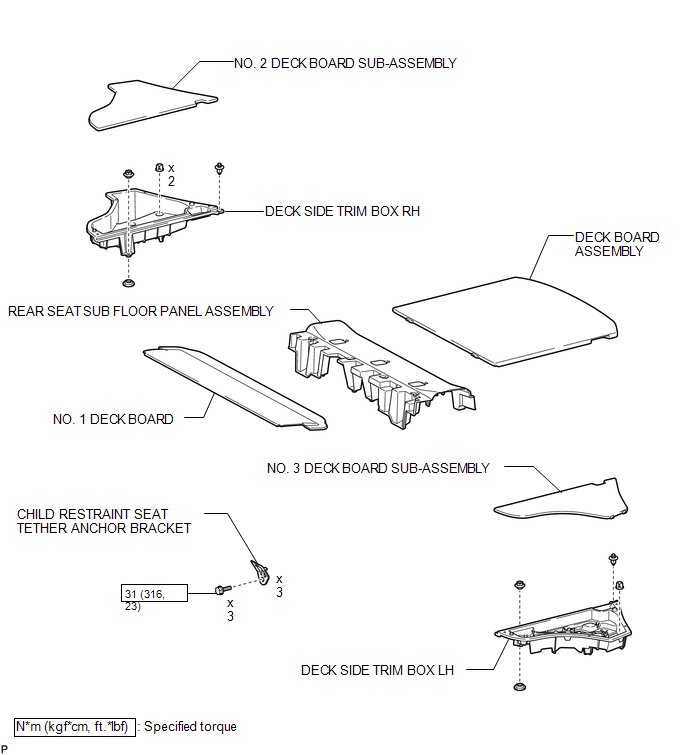
COMPONENTS
ILLUSTRATION
Installation
INSTALLATION
PROCEDURE
1. INSTALL CHILD RESTRAINT SEAT TETHER ANCHOR BRACKET
|
(a) Engage the guide. |
|
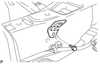
(b) Install the child restraint seat tether anchor bracket with the bolt.
Torque:
31 N·m {316 kgf·cm, 23 ft·lbf}
HINT:
Use the same procedure for the other 2 child restraint seat tether anchor brackets.
2. INSTALL REAR SEAT SUB FLOOR PANEL ASSEMBLY
.gif)
3. INSTALL NO. 1 DECK BOARD
4. INSTALL DECK SIDE TRIM BOX RH
5. INSTALL NO. 2 DECK BOARD SUB-ASSEMBLY
6. INSTALL DECK SIDE TRIM BOX LH
7. INSTALL NO. 3 DECK BOARD SUB-ASSEMBLY
8. INSTALL DECK BOARD ASSEMBLY
Removal
REMOVAL
PROCEDURE
1. REMOVE DECK BOARD ASSEMBLY
.gif)
2. REMOVE NO. 3 DECK BOARD SUB-ASSEMBLY
3. REMOVE DECK SIDE TRIM BOX LH
4. REMOVE NO. 2 DECK BOARD SUB-ASSEMBLY
5. REMOVE DECK SIDE TRIM BOX RH
6. REMOVE NO. 1 DECK BOARD
7. REMOVE REAR SEAT SUB FLOOR PANEL ASSEMBLY
8. REMOVE CHILD RESTRAINT SEAT TETHER ANCHOR BRACKET
|
(a) Remove the bolt. |
|
.png)
(b) Disengage the guide and remove the child restraint seat tether anchor bracket.
HINT:
Use the same procedure for the other 2 child restraint seat tether anchor brackets.
 Seat Belt
...
 Front Passenger Seat Belt Warning Light
Components
COMPONENTS
ILLUSTRATION
Installation
INSTALLATION
PROCEDURE
1. INSTALL ACCESSORY METER ASSEMBLY (w/o Rear View Monitor System)
(a) Connect the connector.
(b) Engage the 2 clam ...
Other materials about Toyota Venza:
Seat Belt Buckle Switch LH Circuit Malfunction (B1656/38)
DESCRIPTION
The seat belt buckle switch LH circuit consists of the center airbag sensor assembly
and front seat inner belt assembly LH.
DTC B1656/38 is stored when a malfunction is detected in the seat belt buckle
switch LH circuit.
DTC No.
...
Inner Rear View Mirror Power Source Circuit
DESCRIPTION
This circuit detects the state of the ignition switch, and sends it to the inner
rear view mirror assembly.
WIRING DIAGRAM
CAUTION / NOTICE / HINT
NOTICE:
Inspect the fuses for circuits related to this system before performing the followin ...
System Diagram
SYSTEM DIAGRAM
Communication Table
Transmitting ECU (Transmitter)
Receiving ECU (Receiver)
Signal
Communication Method
Certification ECU (smart key ECU assembly)
Power management contro ...

0.1131