Toyota Venza: Disassembly
DISASSEMBLY
CAUTION / NOTICE / HINT
HINT:
Use an overhaul stand as necessary.
PROCEDURE
1. REMOVE REAR DIFFERENTIAL FILLER PLUG
|
(a) Remove the rear differential filler plug and gasket. |
|
2. INSPECT RUNOUT OF ELECTRO MAGNETIC CONTROL COUPLING SUB-ASSEMBLY
|
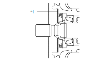
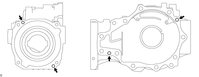
(a) Install a dial indicator and magnetic base perpendicular to the inner side of the electro magnetic control coupling sub-assembly as shown in the illustration. |
|
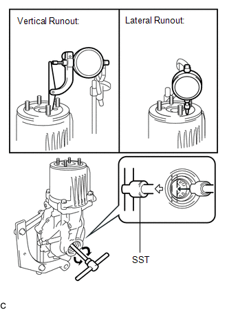
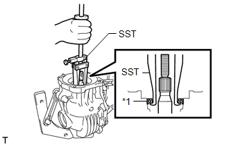
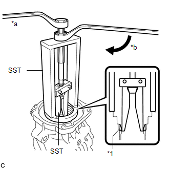
(b) Using SST, rotate the electro magnetic control coupling sub-assembly forward and backward, and measure the vertical runout.
SST: 09564-32011
Maximum Runout:
0.06 mm (0.00236 in.)
If the runout is greater than the maximum value, replace the electro magnetic control coupling sub-assembly.
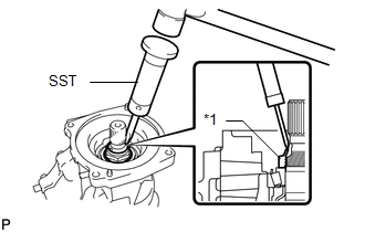
(c) Install a dial indicator and magnetic base perpendicular to the electro magnetic control coupling sub-assembly as shown in the illustration.
(d) Using SST, rotate the electro magnetic control coupling sub-assembly forward and backward, and measure the lateral runout.
SST: 09564-32011
Maximum Runout:
0.07 mm (0.00276 in.)
If the runout is greater than the maximum value, replace the electro magnetic control coupling sub-assembly.
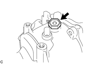
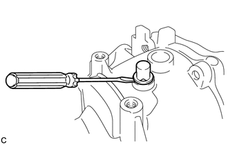
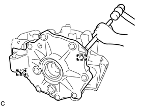
3. REMOVE REAR DIFFERENTIAL CARRIER COVER BREATHER PLUG
|
(a) Using a screwdriver, remove the rear differential carrier cover breather plug. |
|
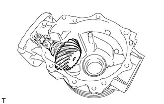
4. REMOVE ELECTRO MAGNETIC CONTROL COUPLING SUB-ASSEMBLY
|
(a) Remove the 4 bolts. |
|
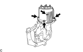
(b) Using a plastic hammer, lightly tap the electro magnetic control coupling sub-assembly to remove it from the rear differential carrier assembly.
NOTICE:
Do not damage the contact surface.
5. REMOVE STUD BOLT
|
(a) Install 2 service nuts to the stud bolt. Text in Illustration
Recommended service nut: Thread Diameter 8.0 mm (0.315 in.) Thread Pitch 1.25 mm (0.0492 in.) |
|
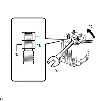
(b) Lock the upper nut using the lower nut.
(c) Turn the lower nut and remove the other 3 stud bolts in the same way.
NOTICE:
Prevent foreign matter from entering the electro magnetic control coupling sub-assembly.
HINT:
If the threads of the electro magnetic control coupling sub-assembly are damaged while removing the stud bolt, replace the electro magnetic control coupling sub-assembly with a new one.
6. REMOVE REAR DIFFERENTIAL DUST DEFLECTOR
|
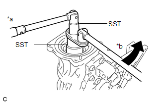
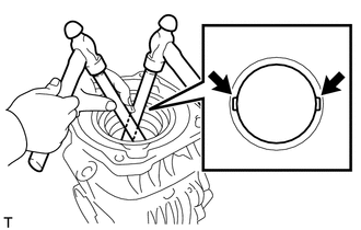
(a) Put matchmarks on the rear differential dust deflector and electro magnetic control coupling sub-assembly. |
|
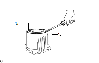
(b) Using a screwdriver, remove the rear differential dust deflector.
Text in Illustration|
*a |
Protective Tape |
|
*b |
Matchmark |
NOTICE:
- Pry around the circumference of the rear differential dust deflector uniformly to prevent deformation.
- Do not damage the end surface of the electro magnetic control coupling sub-assembly.
HINT:
- Tape the screwdriver tip before use.
- If the end surface of the electro magnetic control coupling sub-assembly is damaged while removing the rear differential dust deflector, replace the electro magnetic control coupling sub-assembly with a new one.
7. REMOVE CONNECTOR CLAMP BRACKET
|
(a) Disengage the claw to separate the electro magnetic control coupling wire harness connector. NOTICE: Do not damage the electro magnetic control coupling wire harness. |
|
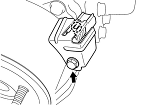
(b) Remove the bolt and connector clamp bracket.
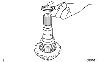
8. REMOVE TRANSMISSION COUPLING CONICAL SPRING WASHER
|
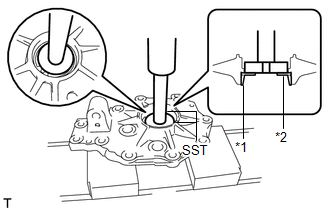
(a) Remove the transmission coupling conical spring washer from the rear differential carrier assembly. Text in Illustration
|
|
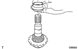
9. REMOVE TRANSMISSION COUPLING SPACER
|
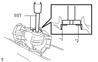
(a) Remove the transmission coupling spacer from the rear differential carrier assembly. Text in Illustration
|
|
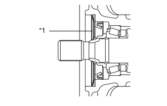
10. INSPECT DIFFERENTIAL RING GEAR BACKLASH
|
(a) Insert a dial indicator and magnetic base through the rear differential filler plug hole, and set it perpendicular to a differential ring gear tooth tip. |
|
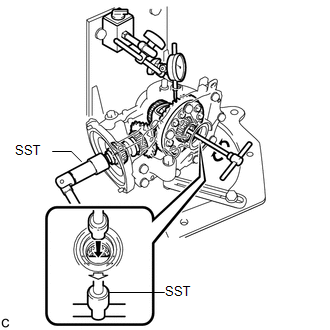
(b) Using SST, hold the differential drive pinion in place.
SST: 09556-16011
(c) Using SST, rotate the rear differential case assembly forward and backward, and measure the backlash.
SST: 09564-32011
Backlash:
0.13 to 0.25 mm (0.00512 to 0.00984 in.)
If the backlash is not within the specification, adjust the side bearing preload or repair as necessary.
HINT:
Measure at 3 or more areas on the circumference of the differential ring gear.
11. INSPECT DIFFERENTIAL DRIVE PINION PRELOAD
|
(a) Using SST and a torque wrench, inspect the differential drive pinion preload (starting torque) of the backlash between the differential drive pinion and differential ring gear. SST: 09556-16011 Standard Drive Pinion Preload: 1.51 to 2.52 N*m (16 to 25 kgf*cm, 14 to 22 in.*lbf) If the differential drive pinion preload is not within the specified range, adjust the differential drive pinion preload or repair as necessary. HINT: For a more accurate measurement, rotate the rear differential case bearing forward and backward before measuring. |
|
12. INSPECT TOTAL PRELOAD
|
(a) Using SST and a torque wrench, inspect the total preload (starting torque) with the teeth of the differential drive pinion and differential ring gear in contact. SST: 09556-16011 Standard Total Preload: 2.80 to 5.34 N*m (29 to 54 kgf*cm, 25 to 47 in.*lbf) If the total preload is not within the specified range, adjust the total preload or repair as necessary. HINT: For a more accurate measurement, rotate the rear differential case bearing forward and backward before measuring. |
|
13. REMOVE REAR DIFFERENTIAL SIDE GEAR SHAFT OIL SEAL
|
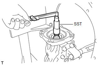
(a) Using SST, remove the 2 rear differential side gear shaft oil seals from the rear differential carrier assembly. SST: 09308-00010 |
|
14. REMOVE DIAPHRAGM OIL SEAL
|
(a) Using SST, remove the diaphragm oil seal from the rear differential carrier assembly. SST: 09308-00010 Text in Illustration
|
|
15. REMOVE REAR DRIVE PINION NUT
|
(a) Using SST and a hammer, release the staked part of the rear drive pinion nut. SST: 09930-00010 Text in Illustration
NOTICE:
|
|
|
(b) Using SST, hold the differential drive pinion in place and remove the rear drive pinion nut from the differential drive pinion. SST: 09556-16011 SST: 09564-16020 Text in Illustration
|
|
16. REMOVE REAR DRIVE PINION FRONT TAPERED ROLLER BEARING
|
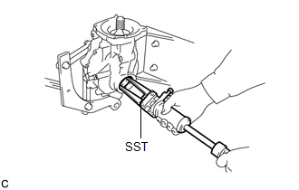
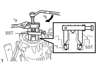
(a) Using SST, remove the rear drive pinion front tapered roller bearing (inner race) from the differential drive pinion. SST: 09556-40010 Text in Illustration
|
|
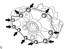
17. REMOVE DIFFERENTIAL SIDE BEARING RETAINER
|
(a) Remove the 10 bolts from the rear differential carrier. |
|
|
(b) Using a brass bar and a hammer, disengage the 2 straight pins and remove the differential side bearing retainer from the rear differential carrier. NOTICE:
|
|
18. REMOVE REAR DIFFERENTIAL CASE ASSEMBLY
|
(a) Remove the rear differential case assembly from the rear differential carrier. |
|
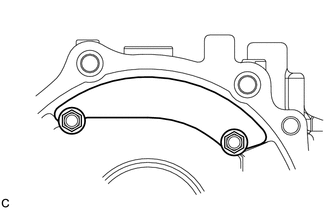
19. REMOVE REAR DIFFERENTIAL BREATHER PLUG OIL DEFLECTOR
|
(a) Remove the 2 bolts and rear differential breather plug oil deflector from the rear differential carrier. |
|
20. REMOVE DIFFERENTIAL DRIVE PINION
|
(a) Remove the differential drive pinion from the rear differential carrier. |
|
21. REMOVE REAR DIFFERENTIAL DRIVE PINION OIL SLINGER
|
(a) Remove the rear differential drive pinion oil slinger from the differential drive pinion. |
|
22. REMOVE REAR DIFFERENTIAL DRIVE PINION BEARING SPACER
|
(a) Remove the rear differential drive pinion bearing spacer from the differential drive pinion. |
|
23. REMOVE REAR DRIVE PINION REAR TAPERED ROLLER BEARING
|
(a) Using SST and a press, press out the rear drive pinion rear tapered roller bearing (inner race) from the differential drive pinion. SST: 09950-00020 NOTICE:
|
|
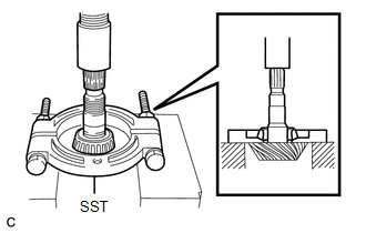
(b) Remove the rear differential drive pinion plate washer.
24. REMOVE REAR DRIVE PINION FRONT TAPERED ROLLER BEARING
|
(a) Using SST, remove the rear drive pinion front tapered roller bearing (outer race) from the rear differential carrier. SST: 09387-00041 09387-01030 09387-01040 SST: 09387-02020 Text in Illustration
|
|
25. REMOVE REAR DRIVE PINION REAR TAPERED ROLLER BEARING
|
(a) Using a brass bar and a hammer, lightly and uniformly tap out the rear drive pinion rear tapered roller bearing (outer race) from the rear differential carrier. NOTICE: Set the brass bar on the notch. |
|
26. REMOVE REAR DIFFERENTIAL CASE BEARING (for LH Side)
|
(a) Using SST and a press, remove the rear differential case bearing (LH side outer race) and rear differential side gear shaft plate washer from the differential side bearing retainer. SST: 09950-60010 09951-00540 SST: 09950-70010 09951-07100 Text in Illustration
|
|
27. REMOVE REAR DIFFERENTIAL CASE BEARING (for RH Side)
|
(a) Using SST and a press, remove the rear differential case bearing (RH side outer race) and rear differential side gear shaft plate washer from the rear differential carrier. SST: 09950-60010 09951-00590 SST: 09950-70010 09951-07100 Text in Illustration
|
|
28. REMOVE STRAIGHT PIN
(a) Remove the 4 straight pins from the rear differential carrier.
29. REMOVE REAR DIFFERENTIAL CASE BEARING (for LH Side)
HINT:
Perform this step only when replacing the rear differential case bearing or rear differential case sub-assembly.
|
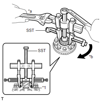
(a) Using SST, remove the rear differential case bearing (LH side inner race) from the rear differential case sub-assembly. SST: 09950-40011 09951-04020 09952-04010 09953-04020 09954-04010 09955-04011 09957-04010 09958-04011 SST: 09950-60010 09951-00340 Text in Illustration
NOTICE: Before using the SST center bolt (09953-04020), apply grease to its threads and tip. HINT:
|
|
30. REMOVE REAR DIFFERENTIAL CASE BEARING (for RH Side)
HINT:
Perform this step only when replacing the rear differential case bearing or rear differential case sub-assembly.
|
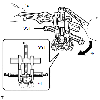
(a) Using SST, remove the rear differential case bearing (RH side inner race) from the rear differential case sub-assembly. SST: 09950-40011 09951-04020 09952-04010 09953-04020 09954-04010 09955-04061 09957-04010 09958-04011 SST: 09950-60010 09951-00370 Text in Illustration
NOTICE: Before using the SST center bolt (09953-04020), apply grease to its threads and tip. HINT:
|
|
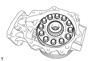
31. REMOVE DIFFERENTIAL RING GEAR
(a) Secure the rear differential case sub-assembly in a vise between aluminum plates.
NOTICE:
Do not overtighten the vise.
|
(b) Put matchmarks on the rear differential case sub-assembly and differential ring gear. Text in Illustration
|
|
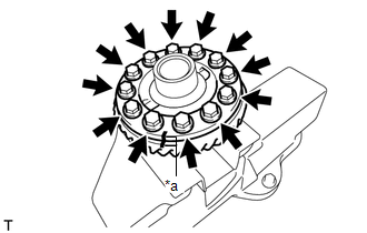
(c) Remove the 12 rear differential case bolts.
(d) Using a plastic hammer, lightly and uniformly tap the outer circumference of the differential ring gear to remove it from the rear differential case sub-assembly.
NOTICE:
- Do not drop the differential ring gear.
- If the differential drive pinion or differential ring gear is damaged, replace them both.
HINT:
If it is difficult to remove, tap the outer circumference of the differential ring gear using a brass bar and a hammer.
32. INSPECT DIFFERENTIAL PINION AND SIDE GEAR
(a) Check the differential pinion gears and differential side gears for wear.
If the differential pinion gears and differential side gears are damaged, replace the rear differential case sub-assembly.
33. INSPECT DIFFERENTIAL CASE
(a) Check the differential case for cracks or damage.
If the differential case is damaged, replace the rear differential case sub-assembly.
 Removal
REMOVAL
PROCEDURE
1. DRAIN DIFFERENTIAL OIL
(a) Using a 10 mm hexagon wrench, remove the rear differential carrier
cover plug and gasket.
...
 Reassembly
REASSEMBLY
CAUTION / NOTICE / HINT
HINT:
Use an overhaul stand as necessary.
PROCEDURE
1. INSTALL DIFFERENTIAL RING GEAR
(a) Clean the contact surfaces of the rear differential case sub-assembly ...
Other materials about Toyota Venza:
Disassembly
DISASSEMBLY
PROCEDURE
1. REMOVE POSITION INDICATOR HOUSING SUB-ASSEMBLY
(a) Remove the shift lever cap from the position indicator housing sub-assembly.
(b) Disengage the 4 claws and remove the position indicator housing sub-assembly.
...
Poor Sound Quality in All Modes (Low Volume)
PROCEDURE
1.
CHECK AUDIO SETTINGS
(a) Set treble, middle and bass to the initial values and check that the sound
is normal.
OK:
The sound returns to normal.
HINT:
Sound quality adjustment measures vary according to the ...
Touch Sensor Circuit
DESCRIPTION
When the power back door ECU receives a jam signal from the touch sensor while
the power back door is operating, the ECU reverses the back door operation and opens
the door.
WIRING DIAGRAM
PROCEDURE
1.
READ VALUE US ...

0.1301