Toyota Venza: Reassembly
REASSEMBLY
PROCEDURE
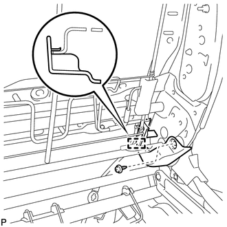
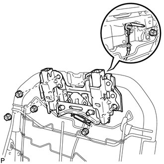
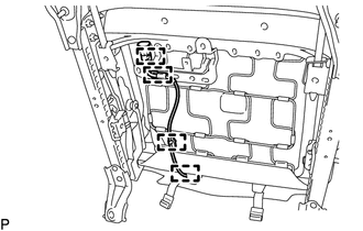
1. INSTALL FRONT SEAT WIRE
|
(a) Engage the 2 clamps to install the front seat wire. |
|
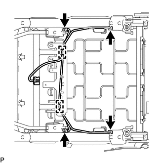
(b) Connect the 4 connectors.
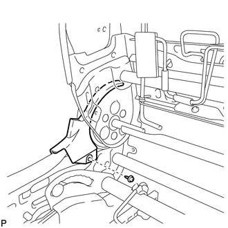
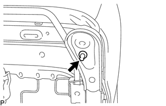
2. INSTALL OCCUPANT CLASSIFICATION ECU
.gif)
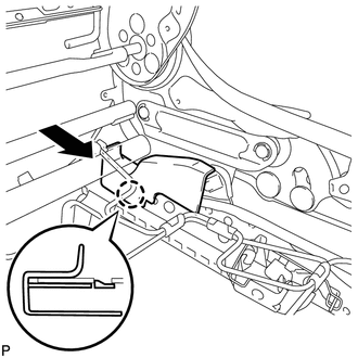
3. INSTALL FRONT LOWER SEAT CUSHION SHIELD LH
|
(a) Engage the claw to install the front lower seat cushion shield LH as shown in the illustration. |
|
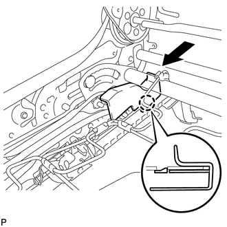
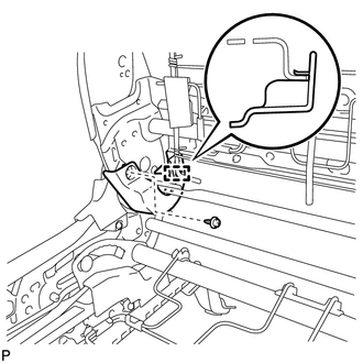
4. INSTALL FRONT LOWER SEAT CUSHION SHIELD RH
|
(a) Engage the claw to install the front lower seat cushion shield RH as shown in the illustration. |
|
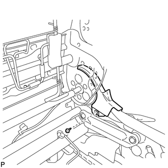
5. INSTALL UPPER RECLINING ADJUSTER INSIDE COVER LH
|
(a) Install the upper reclining adjuster inside cover LH with the screw. |
|
6. INSTALL LOWER RECLINING ADJUSTER INSIDE COVER LH
|
(a) Engage the guide. |
|
(b) Install the lower reclining adjuster inside cover LH with the screw.
7. INSTALL UPPER RECLINING ADJUSTER INSIDE COVER RH
|
(a) Install the upper reclining adjuster inside cover RH with the screw. |
|
8. INSTALL LOWER RECLINING ADJUSTER INSIDE COVER RH
|
(a) Engage the guide. |
|
(b) Install the lower reclining adjuster inside cover RH with the screw.
9. INSTALL LOWER ACTIVE HEADREST UNIT
|
(a) Install the lower active headrest unit with the 2 nuts. Torque: 5.0 N·m {51 kgf·cm, 44 in·lbf} |
|
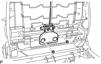
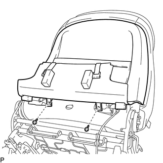
10. INSTALL UPPER ACTIVE HEADREST UNIT
|
(a) Install the upper active headrest unit with the 4 nuts. Torque: 14 N·m {143 kgf·cm, 10 ft·lbf} |
|
(b) Engage the cable clamp to connect the cable of the lower active headrest unit with the nut.
Torque:
5.0 N·m {51 kgf·cm, 44 in·lbf}
11. INSTALL FRONT SEAT SIDE AIRBAG ASSEMBLY
HINT:
Use the same procedure as for the LH side (See page
).
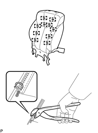
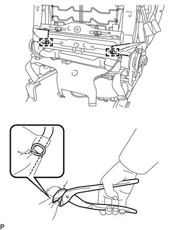
12. INSTALL SEPARATE TYPE FRONT SEATBACK COVER
|
(a) Using hog ring pliers, install the separate type front seatback cover to the separate type front seatback pad with 10 new hog rings. NOTICE:
|
|
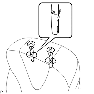
13. INSTALL SEPARATE TYPE FRONT SEATBACK COVER WITH PAD
(a) Temporarily install the separate type front seatback cover with pad to the front seat frame assembly with adjuster.
|
(b) Engage the 4 claws to install the 2 front seat headrest supports. |
|
|
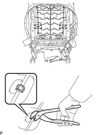
(c) Using hog ring pliers, install 2 new hog rings. NOTICE:
|
|
|
(d) Using hog ring pliers, install 2 new hog rings. NOTICE:
|
|
|
(e) Engage the 4 hooks. |
|
|
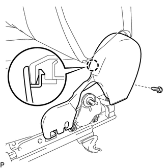
(f) Engage the guide to install the bracket of the separate type front seatback cover with the nut. Text in Illustration
Torque: 8.0 N·m {82 kgf·cm, 71 in·lbf} NOTICE:
|
|
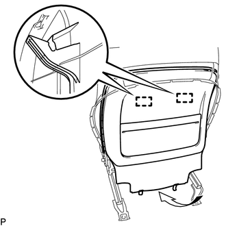
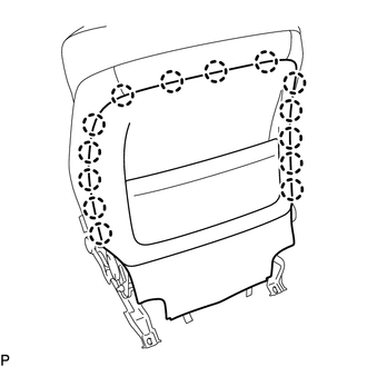
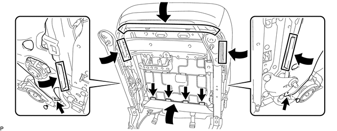
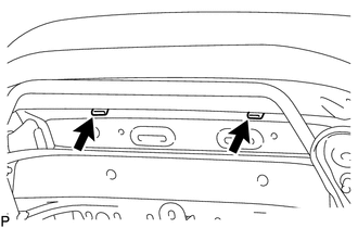
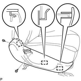
14. INSTALL FRONT SEATBACK BOARD SUB-ASSEMBLY
|
(a) Engage the 2 guides as shown in the illustration. |
|
|
(b) Engage the 14 claws. |
|
|
(c) Install the front seatback board sub-assembly with the 2 screws. |
|
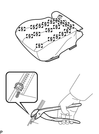
15. INSTALL SEPARATE TYPE FRONT SEAT CUSHION COVER
|
(a) Using hog ring pliers, install the separate type front seat cushion cover to the separate type front seat cushion pad with 18 new hog rings. NOTICE:
|
|
16. INSTALL SEPARATE TYPE FRONT SEAT CUSHION COVER WITH PAD
|
(a) Temporarily install the separate type front seat cushion cover with pad to the front seat frame assembly with adjuster. |
|
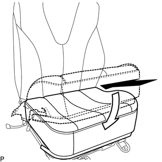
(b) Engage each hook as shown in the illustration.
(c) Install the 2 clips.
|
(d) Engage the 4 clamps to connect the front seat side airbag assembly wire harness. |
|
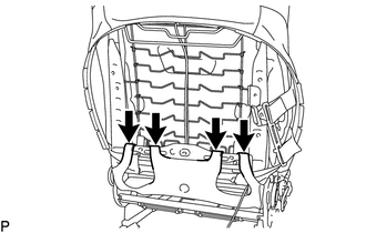
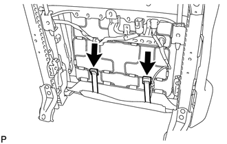
17. INSTALL FRONT SEAT CUSHION PROTECTOR
|
(a) Install the 2 front seat cushion protectors. |
|
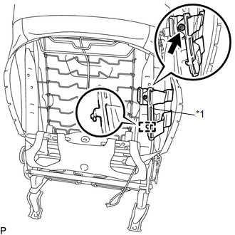
18. INSTALL FRONT INNER SEAT CUSHION SHIELD
|
(a) Engage the guide. |
|
|
(b) Engage the claw. |
|
(c) Install the front inner seat cushion shield with the screw.
19. INSTALL FRONT SEAT BELT ANCHOR PLATE
20. INSTALL FRONT SEAT INNER BELT ASSEMBLY
21. INSTALL FRONT SEAT CUSHION SHIELD
|
(a) Engage the 2 guides and claw to install the front seat cushion shield. |
|
(b) Install the 2 screws.
|
(c) Engage the 2 hooks. |
|
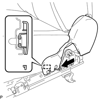
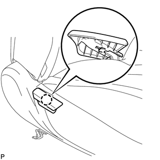
22. INSTALL RECLINING ADJUSTER RELEASE HANDLE
|
(a) Engage the claw to install the reclining adjuster release handle. |
|
23. INSTALL SEAT ADJUSTER COVER CAP
|
(a) Install the seat adjuster cover cap. HINT: Use the same procedure for the RH side and LH side. |
|
 Removal
REMOVAL
PROCEDURE
1. PRECAUTION
CAUTION:
Be sure to read Precaution thoroughly before servicing (See page
).
If the front seat side airbag assembly was deployed, replace the front ...
 Installation
INSTALLATION
PROCEDURE
1. INSTALL FRONT SEAT ASSEMBLY
(a) Place the front seat assembly in the cabin.
NOTICE:
Be careful not to damage the vehicle body.
(b) Connect each connector under the fron ...
Other materials about Toyota Venza:
Installation
INSTALLATION
PROCEDURE
1. INSTALL REAR NO. 3 SPEAKER ASSEMBLY
(a) Install the rear No. 3 speaker assembly with the 2 bolts.
(b) Engage the clamp.
2. INSTALL ROOF SIDE INNER GARNISH ASSEMBLY LH
...
Customize Parameters
CUSTOMIZE PARAMETERS
HINT:
The following items can be customized.
NOTICE:
After confirming whether the items requested by the customer are applicable
or not for customization, perform customizing operations.
Be sure to record the current se ...
Inspection
INSPECTION
PROCEDURE
1. INSPECT FRONT SEAT OUTER BELT ASSEMBLY
NOTICE:
Do not disassemble the retractor.
(a) Before installing the front seat outer belt assembly, check the ELR.
(1) When the inclination of the retractor is 15° or less, check that the ...

0.1648