Toyota Venza: Replacement
REPLACEMENT
PROCEDURE
1. RECOVER REFRIGERANT FROM REFRIGERATION SYSTEM
(a) Start up the engine.
(b) Turn the A/C switch on.
(c) Operate the cooler compressor at an engine speed of approximately 1000 rpm for 5 to 6 minutes to circulate the refrigerant. This causes most of the compressor oil from the various components of the A/C system to collect in the A/C compressor.
(d) Stop the engine.
(e) Recover the refrigerant from the A/C system using a refrigerant recovery unit.
2. CHARGE WITH REFRIGERANT
(a) Perform vacuum purging using a vacuum pump.
(b) Charge with refrigerant HFC-134a (R134a).
Standard:
450 to 550 g (15.9 to 19.4 oz.)
SST: 09985-20010
09985-02010
09985-02050
09985-02060
09985-02070
09985-02080
09985-02090
09985-02110
09985-02130
09985-02140
09985-02150
NOTICE:
Do not turn the A/C switch on before charging with refrigerant. Doing so will cause the compressor to work without refrigerant, resulting in overheating of the compressor.
HINT:
Ensure that sufficient refrigerant is available to recharge the system when using a refrigerant recovery unit. Refrigerant recovery units are not always able to recover 100% of the refrigerant from an A/C system.
3. WARM UP ENGINE
(a) Keep the A/C switch on for at least 2 minutes to warm up the compressor.
NOTICE:
Be sure to warm up the compressor when turning the A/C switch on after removing and installing the cooler refrigerant lines (including the compressor), to prevent damage to the compressor.
4. INSPECT FOR REFRIGERANT LEAK
(a) After recharging with refrigerant, inspect for refrigerant leaks using a halogen leak detector.
(b) Carry out the test under the following conditions:
- Turn the ignition switch off.
- Secure good ventilation (the halogen leak detector may react to volatile gases which are not refrigerant, such as evaporated gasoline and exhaust gas).
- Repeat the test 2 or 3 times.
- Make sure that there is some refrigerant remaining in the refrigeration
system.
When the compressor is off: approx. 392 to 588 kPa (4.0 to 6.0 kgf/cm2, 57 to 85 psi)
|
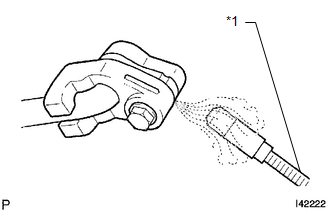
(c) Using a halogen leak detector, inspect for refrigerant leaks from the refrigerant lines. Text in Illustration
|
|
|
(d) Bring the halogen leak detector close to the drain hose with the detector's power off, and then turn the detector on. Text in Illustration
HINT:
|
|
(e) If a refrigerant leak is not detected from the drain hose, remove the blower motor control from the cooling unit. Insert the halogen leak detector sensor into the unit and perform the test.
(f) Disconnect the pressure switch connector and leave it for approximately 20 minutes. Bring the halogen leak detector close to the pressure switch and perform the test.
 On-vehicle Inspection
ON-VEHICLE INSPECTION
PROCEDURE
1. INSPECT REFRIGERANT PRESSURE WITH MANIFOLD GAUGE SET
HINT:
This is a method where a manifold gauge set is used to help locate the problem.
(a) Read the manifold ...
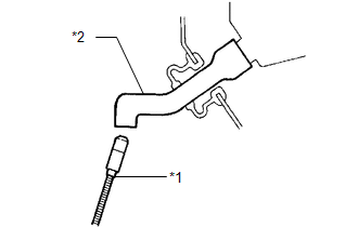
 Refrigerant Line
Components
COMPONENTS
ILLUSTRATION
ILLUSTRATION
...
Other materials about Toyota Venza:
Automatic anti-glare function
Responding to the level of brightness of the headlights of vehicles behind, the
reflected light is automatically reduced.
Changing automatic anti-glare function mode ON/OFF
When the automatic anti-glare function is in ON mode, the indicator illuminates.
...
Display does not Dim when Light Control Switch is Turned ON
PROCEDURE
1.
CHECK IMAGE QUALITY SETTING
(a) Turn the light control switch to the tail or head position.
(b) Check that the daytime screen setting on the display adjustment screen is
set to on.
Result
...
Data List / Active Test
DATA LIST / ACTIVE TEST
1. DATA LIST
HINT:
Using the Techstream to read the Data List allows the values or states of switches,
sensors, actuators and other items to be read without removing any parts. This non-intrusive
inspection can be very useful bec ...

0.1158