Toyota Venza: Disassembly
DISASSEMBLY
PROCEDURE
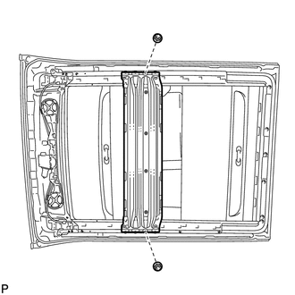
1. REMOVE SLIDING ROOF HOUSING CENTER FRAME
|
(a) Remove the 2 nuts and sliding roof housing center frame. |
|
2. REMOVE NO. 4 SUNSHADE TRIM SUB-ASSEMBLY
|
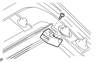
(a) Remove the screw and rear sliding roof sunshade stopper LH. HINT: Use the same procedure for the RH side and the LH side. |
|
|
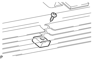
(b) Remove the screw and center sliding roof sunshade stopper LH. HINT: Use the same procedure for the RH side and the LH side. |
|
|
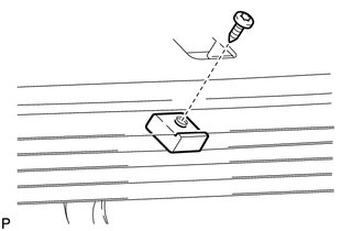
(c) Remove the screw and front sliding roof sunshade stopper LH. HINT: Use the same procedure for the RH side and the LH side. |
|
|
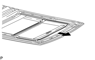
(d) Slide and remove the No. 4 sunshade trim sub-assembly. |
|
3. REMOVE NO. 3 SUNSHADE TRIM SUB-ASSEMBLY
|
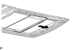
(a) Slide and remove the No. 3 sunshade trim sub-assembly. |
|
4. REMOVE NO. 2 SUNSHADE TRIM SUB-ASSEMBLY
|
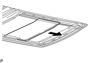
(a) Slide and remove the No. 2 sunshade trim sub-assembly. |
|
5. REMOVE NO. 1 SUNSHADE TRIM SUB-ASSEMBLY
|
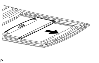
(a) Slide and remove the No. 1 sunshade trim sub-assembly. |
|
 Removal
REMOVAL
PROCEDURE
1. REMOVE NO. 1 SLIDING ROOF GLASS SUB-ASSEMBLY
(a) Fully open the No. 2 sliding roof glass sub-assembly.
(b) Using a T20 "TORX" socket wrench, remove the 6 ...
 Reassembly
REASSEMBLY
PROCEDURE
1. INSTALL NO. 1 SUNSHADE TRIM SUB-ASSEMBLY
(a) Slide and install the No. 1 sunshade trim sub-assembly.
2. INSTALL NO ...
Other materials about Toyota Venza:
Operation Check
OPERATION CHECK
1. CHECK WINDOW LOCK SWITCH
HINT:
Before performing the window lock switch operation check, make sure that the
window lock switch is off (the switch is not pushed in).
(a) Check that the front passenger and rear windows cannot be operat ...
Diagnostic Trouble Code Chart
DIAGNOSTIC TROUBLE CODE CHART
HINT:
If a trouble code is displayed during the DTC check, inspect the trouble areas
listed for that code. For details of the code, refer to the "See page" below.
Power Steering System
DTC Code
...
Steering Pad Switch Circuit
DESCRIPTION
This circuit sends an operation signal from the steering pad switch assembly
to the navigation receiver assembly.
If there is an open in the circuit, the audio system cannot be operated using
the steering pad switch assembly.
If there is a s ...

0.1195