Toyota Venza: Calibration
CALIBRATION
1. SELECT COMPASS DISPLAY MODE
(a) The AUTO switch allows selection of the compass display.
2. PERFORM CALIBRATION
(a) Because each vehicle has its own magnetic field, calibration should be performed. The calibration function is used to compensate for the residual magnetism of the vehicle.
3. WHEN COMPASS IS MAGNETIZED
(a) The compass or vehicle may become magnetized while the vehicle is being shipped. As a result, it is necessary to perform calibration for the compass before the vehicle is delivered to the customer. If calibration cannot be performed successfully (calibration cannot be completed in spite of driving around several times), it may caused by excessive magnetization of the vehicle. Demagnetize the vehicle using a demagnetizer and perform calibration again.
4. SET COMPASS
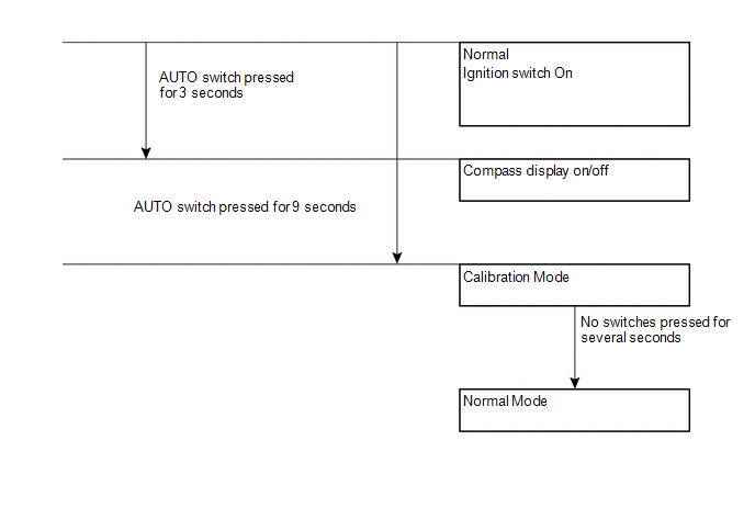
5. CALIBRATION MODE
(a) When the compass is in normal mode, pressing the AUTO switch for 9 seconds will activate the calibration mode.
(b) Drive the vehicle in a circle at a speed of 8 km/h (5 mph) or less.
(c) After driving around in a circle 1 to 3 times, the direction (N, NE, E, SE, S, SW, W or NW) will be displayed on the compass display. This indicates that calibration has finished.
HINT:
After calibration is performed, it is not necessary to repeat the calibration procedure unless magnetic field of the vehicle changes drastically. If the magnetic field changes drastically, the compass display will indicate "C".
 System Diagram
SYSTEM DIAGRAM
...
 Problem Symptoms Table
PROBLEM SYMPTOMS TABLE
Use the table below to help determine the cause of problem symptoms. If multiple
suspected areas are listed, the potential causes of the symptoms are listed in order
of pro ...
Other materials about Toyota Venza:
Disassembly
DISASSEMBLY
PROCEDURE
1. REMOVE GENERATOR REAR END COVER
(a) Remove the 3 nuts and generator rear end cover.
2. REMOVE TERMINAL INSULATOR
(a) Remove the terminal insulator from the gener ...
GPS Mark is not Displayed
PROCEDURE
1.
CHECK CABIN
(a) Check the cabin for any object that might interrupt radio reception or additional
devices which use radio waves on the instrument panel. If such an object exists,
remove it and check if the GPS ...
Installation
INSTALLATION
PROCEDURE
1. INSTALL CONSOLE BOX ASSEMBLY
(a) Connect the connectors.
(b) Engage the 2 claws.
(c) Install the screw and 2 clips.
...

0.1446