Toyota Venza: Reassembly
REASSEMBLY
PROCEDURE
1. INSTALL MULTIPLEX NETWORK DOOR ECU
|
(a) Connect the connector and install the multiplex network door ECU. |
|
.png)
|
(b) Install the flat cable connector as shown in the illustration. |
|
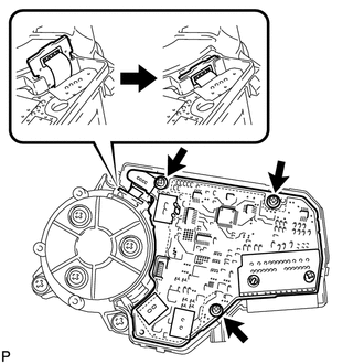
(c) Install the 3 screws.
|
(d) Engage the 4 claws to install the cover. |
|
.png)
 Disassembly
DISASSEMBLY
CAUTION / NOTICE / HINT
NOTICE:
When disassembling the multiplex network door ECU, eliminate static electricity
by touching the vehicle body to prevent the components from being damag ...
 Installation
INSTALLATION
PROCEDURE
1. INSTALL POWER BACK DOOR UNIT ASSEMBLY
(a) Install the power back door unit with the 4 bolts.
Torque:
13 N·m {133 kgf·cm, 10 ft·lbf}
...
Other materials about Toyota Venza:
Installation
INSTALLATION
PROCEDURE
1. INSTALL ROOF DRIP SIDE FINISH MOULDING CLIP (w/o Sliding Roof)
NOTICE:
If reusing the clips, do not remove the double-sided tape remaining
on the clips and where the clips will be installed on the body.
If installi ...
Certification ECU Communication Stop Mode
DESCRIPTION
Detection Item
Symptom
Trouble Area
Certification ECU Communication Stop Mode
"Smart Access/Smart Key/Wireless Tuner" is not displayed on
"CAN Bus Check&q ...
Removal
REMOVAL
CAUTION / NOTICE / HINT
NOTICE:
When disconnecting the steering intermediate shaft assembly and pinion shaft
of steering gear assembly, be sure to place matchmarks before servicing.
PROCEDURE
1. PLACE FRONT WHEELS FACING STRAIGHT AHEAD
2. SECUR ...

0.1433