Toyota Venza: Disassembly
DISASSEMBLY
CAUTION / NOTICE / HINT
NOTICE:
When disassembling the multiplex network door ECU, eliminate static electricity by touching the vehicle body to prevent the components from being damaged.
PROCEDURE
1. REMOVE MULTIPLEX NETWORK DOOR ECU
|
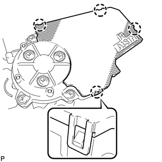
(a) Disengage the 4 claws and remove the cover. |
|
|
(b) Remove the 3 screws. |
|
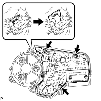
(c) Remove the flat cable connector as shown in the illustration.
|
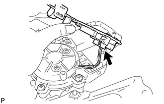
(d) Disconnect the connector and remove the multiplex network door ECU. |
|
 Removal
REMOVAL
PROCEDURE
1. REMOVE REAR DOOR SCUFF PLATE LH
2. DISCONNECT REAR DOOR OPENING TRIM WEATHERSTRIP LH
3. REMOVE TONNEAU COVER ASSEMBLY (w/ Tonneau Cover)
4. REMOVE DECK BOARD ASSEMBL ...
 Reassembly
REASSEMBLY
PROCEDURE
1. INSTALL MULTIPLEX NETWORK DOOR ECU
(a) Connect the connector and install the multiplex network door ECU.
...
Other materials about Toyota Venza:
Cellular Phone Registration Failure
PROCEDURE
1.
CHECK USAGE CONDITION
(a) Check that the vehicle and cellular phone meet the following conditions:
NOTICE:
If changing cellular phone settings, updating software, etc. is necessary, make
sure to obtain the per ...
Operation Check
OPERATION CHECK
1. AUTOMATIC LIGHT CONTROL SYSTEM OPERATION CHECK
(a) Turn the ignition switch to ON.
(b) Turn the light control switch to the AUTO position.
(c) Cover the automatic light control sensor.
(d) Check that the taillights and low beam headligh ...
Security Indicator Light Circuit
DESCRIPTION
The security indicator light blinks continuously due to a continuous signal received
from the transponder key ECU assembly while in the armed state.
WIRING DIAGRAM
CAUTION / NOTICE / HINT
NOTICE:
If the transponder key ECU assembly is repl ...

0.1842