Toyota Venza: Installation
INSTALLATION
PROCEDURE
1. INSTALL POWER BACK DOOR UNIT ASSEMBLY
|
(a) Install the power back door unit with the 4 bolts. Torque: 13 N·m {133 kgf·cm, 10 ft·lbf} |
|
.png)
(b) Connect the connector.
2. INSTALL POWER BACK DOOR ROD
(a) When reusing the power back door rod:
|
(1) Install the 2 stop rings to the power back door rod. |
|
|
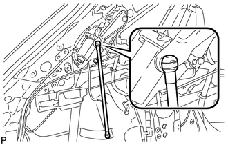
(b) Engage the power back door rod. |
|
|
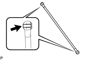
(c) Install the power back door rod. |
|
.png)
(d) Check that the power back door rod is engaged in the ball joint and that the power back door rod cannot be pulled out.
3. INSTALL ROOF SIDE INNER GARNISH ASSEMBLY LH
.gif)
4. INSTALL DECK TRIM SIDE PANEL ASSEMBLY LH
5. CONNECT REAR SEAT OUTER BELT ASSEMBLY LH
6. INSTALL LUGGAGE HOLD BELT STRIKER ASSEMBLY LH
7. INSTALL RECLINING REMOTE CONTROL BEZEL LH
8. INSTALL REAR SEAT ASSEMBLY LH
9. CONNECT REAR SEAT NO. 2 RECLINING CONTROL CABLE SUB-ASSEMBLY
10. INSTALL REAR SEAT OUTER TRACK BRACKET COVER LH
11. INSTALL REAR SEAT INNER TRACK BRACKET COVER LH
12. INSTALL REAR SEAT HEADREST ASSEMBLY LH
13. INSTALL REAR FLOOR FINISH PLATE
14. INSTALL REAR SEAT SUB FLOOR PANEL ASSEMBLY
15. INSTALL NO. 1 DECK BOARD
16. INSTALL DECK SIDE TRIM BOX LH
17. INSTALL NO. 3 DECK BOARD SUB-ASSEMBLY
18. INSTALL DECK SIDE TRIM BOX RH
19. INSTALL NO. 2 DECK BOARD SUB-ASSEMBLY
20. INSTALL DECK BOARD ASSEMBLY
21. INSTALL TONNEAU COVER ASSEMBLY (w/ Tonneau Cover)
22. CONNECT REAR DOOR OPENING TRIM WEATHERSTRIP LH
23. INSTALL REAR DOOR SCUFF PLATE LH
24. INITIALIZE EASY CLOSER SYSTEM
(See page )
25. INITIALIZE POWER BACK DOOR SYSTEM
(See page )
 Reassembly
REASSEMBLY
PROCEDURE
1. INSTALL MULTIPLEX NETWORK DOOR ECU
(a) Connect the connector and install the multiplex network door ECU.
...
 Power Back Door Main Switch
Components
COMPONENTS
ILLUSTRATION
Inspection
INSPECTION
PROCEDURE
1. INSPECT POWER BACK DOOR MAIN SWITCH
(a) Check that the switch function.
(1) Measure the resistance according to th ...
Other materials about Toyota Venza:
USB Device Malfunction (B1585)
DESCRIPTION
This DTC is stored when a malfunction occurs in a connected device.
DTC No.
DTC Detection Condition
Trouble Area
B1585
When any of the following conditions is met:
A non m ...
On-vehicle Inspection
ON-VEHICLE INSPECTION
PROCEDURE
1. INSPECT COOLING FAN OPERATION AT LOW TEMPERATURES (Below 83°C (181°F))
(a) Turn the ignition switch to ON.
(b) Check that the cooling fans stop.
If not, check the cooling fan relays and engine coolant temperature senso ...
Vehicle identification
- Vehicle identification number
The vehicle identification number (VIN) is the legal identifier for your vehicle.
This is the primary identification number for your Toyota. It is used in registering
the ownership of your vehicle.
This number is s ...

0.13