Toyota Venza: Back Door Entry Lock and Unlock Functions do not Operate
DESCRIPTION
When the back door entry lock and unlock functions do not operate, one of the following may be malfunctioning: 1) power door lock control system; 2) outside electrical key oscillator (for rear side); 3) certification ECU (smart key ECU assembly), or 4) back door opener switch assembly.
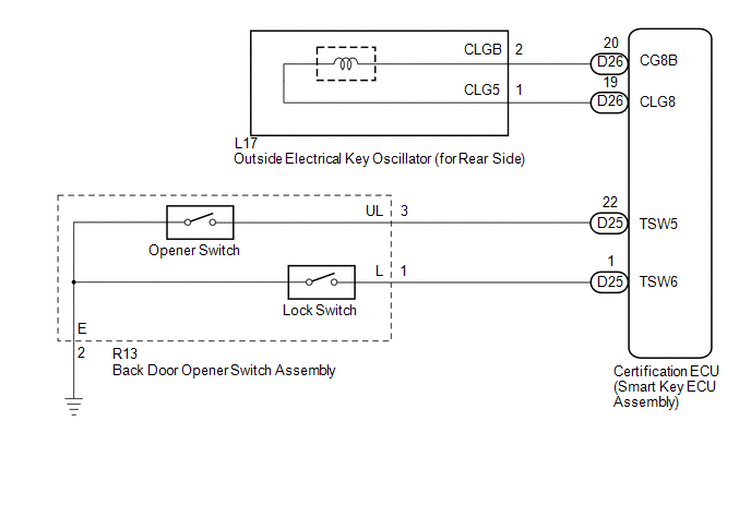
WIRING DIAGRAM
CAUTION / NOTICE / HINT
NOTICE:
- The smart key system (for entry function) uses a multiplex communication
system (LIN communication system) and CAN communication system. Inspect
the communication function by following How to Proceed with Troubleshooting
(See page
.gif) ). Troubleshoot the smart
). Troubleshoot the smart
key system (for entry function) after confirming that the communication system is functioning properly. - Confirm that another key is not in the cabin.
PROCEDURE
|
1. |
CHECK POWER DOOR LOCK OPERATION |
(a) When the door control switch on the master switch assembly is operated, check
that the doors unlock and lock according to switch operation (See page
).
OK:
Door locks operate normally.
| NG | .gif) |
GO TO POWER DOOR LOCK CONTROL SYSTEM (Proceed to Problem Symptoms Table) |
|
.gif)
|
2. |
READ VALUE USING TECHSTREAM |
(a) Connect the Techstream to the DLC3.
(b) Turn the engine switch on (IG).
(c) Turn the Techstream on.
(d) Enter the following menus: Body Electrical / Smart Key / Data List.
(e) Read the Data List according to the display on the Techstream.
Smart Key (Certification ECU (Smart Key ECU Assembly))|
Tester Display |
Measurement Item/Display |
Normal Condition |
Diagnostic Note |
|---|---|---|---|
|
Tr/B-Door Lock SW |
Back door opener switch assembly (lock switch) / ON or OFF |
ON: Back door opener switch assembly (lock switch) pushed OFF: Back door opener switch assembly (lock switch) not pushed |
- |
|
Tr/B-Door Unlock SW |
Back door opener switch assembly (opener switch) / ON or OFF |
ON: Back door opener switch assembly (opener switch) pushed OFF: Back door opener switch assembly (opener switch) not pushed |
- |
OK:
On the Techstream screen, the display changes between ON and OFF as shown in the chart above.
| NG | |
GO TO STEP 7 |
|
|
3. |
CHECK WAVE ENVIRONMENT |
|
(a) Bring the key near the outside electrical key oscillator (for rear side), and perform an entry back door open and entry lock functions check. NOTICE: If the key is brought within 0.2 m (0.656 ft.) of the rear bumper, communication is not possible. HINT:
OK: Entry functions operate normally. |
|
.png)
| OK | |
AFFECTED BY WAVE INTERFERENCE |
|
|
4. |
PERFORM KEY DIAGNOSTIC MODE INSPECTION |
|
(a) Diagnostic mode inspection (outside electrical key oscillator (for rear side)) (1) Connect the Techstream to the DLC3. (2) Turn the engine switch on (IG). (3) Turn the Techstream on. (4) Enter the following menus: Body Electrical / Smart Key / Key Communication Check / Overhead + Back Door. (5) When the key is held at the same height as the rear bumper upper surface and aligned with the center of the rear of the vehicle, check that the wireless door lock buzzer sounds. HINT: If the buzzer sounds, it can be determined that the outside electrical key oscillator (for rear side) is operating normally. OK: Wireless door lock buzzer sounds. |
|
.png)
| OK | |
REPLACE CERTIFICATION ECU (SMART KEY ECU ASSEMBLY) |
|
|
5. |
CHECK HARNESS AND CONNECTOR (CERTIFICATION ECU - OUTSIDE ELECTRICAL KEY OSCILLATOR) |
(a) Disconnect the certification ECU (smart key ECU assembly) connector.
|
(b) Disconnect the outside electrical key oscillator (for rear side) connector. |
|
.png)
(c) Measure the resistance according to the value(s) in the table below.
Standard Resistance:
|
Tester Connection |
Condition |
Specified Condition |
|---|---|---|
|
D26-19 (CLG8) - L17-1 (CLG5) |
Always |
Below 1 Ω |
|
D26-20 (CG8B) - L17-2 (CLGB) |
Always |
Below 1 Ω |
|
D26-19 (CLG8) - Body ground |
Always |
10 kΩ or higher |
|
D26-20 (CG8B) - Body ground |
Always |
10 kΩ or higher |
|
L17-1 (CLG5) - Body ground |
Always |
10 kΩ or higher |
|
L17-2 (CLGB) - Body ground |
Always |
10 kΩ or higher |
|
*1 |
Front view of wire harness connector (to Certification ECU (Smart Key ECU Assembly)) |
|
*2 |
Front view of wire harness connector (to Outside Electrical Key Oscillator (for Rear Side)) |
| NG | |
REPAIR OR REPLACE HARNESS OR CONNECTOR |
|
|
6. |
INSPECT OUTSIDE ELECTRICAL KEY OSCILLATOR (for Rear Side) |
|
(a) Measure the resistance according to the value(s) in the table below. Standard Resistance:
|
|
.png)
| OK | |
REPLACE CERTIFICATION ECU (SMART KEY ECU ASSEMBLY) |
| NG | |
REPLACE OUTSIDE ELECTRICAL KEY OSCILLATOR (for Rear Side) |
|
7. |
CHECK HARNESS AND CONNECTOR (BACK DOOR OPENER SWITCH - BODY GROUND) |
|
(a) Disconnect the back door opener switch assembly connector. |
|
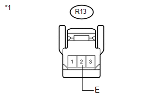
(b) Measure the resistance according to the value(s) in the table below.
Standard Resistance:
|
Tester Connection |
Condition |
Specified Condition |
|---|---|---|
|
R13-2 (E) - Body ground |
Always |
Below 1 Ω |
|
*1 |
Front view of wire harness connector (to Back Door Opener Switch Assembly)) |
| OK | |
REPLACE BACK DOOR OPENER SWITCH ASSEMBLY |
| NG | |
REPAIR OR REPLACE HARNESS OR CONNECTOR |
 Back Door Entry Unlock Function does not Operate
DESCRIPTION
If the entry back door open function does not operate but the back door entry
lock function operates, the communication between the vehicle and key is normal.
As a faulty part, the ba ...
 Back Door Entry Lock Function does not Operate
DESCRIPTION
If the back door entry lock function does not operate but the back door open
function operates, the communication between the vehicle and key is normal. As a
faulty part, the entry lo ...
Other materials about Toyota Venza:
Precaution
PRECAUTION
1. INITIALIZATION
NOTICE:
Perform the Registration (VIN registration) when replacing the ECM (See page
).
HINT:
Reset memory or initialization cannot be completed by only disconnecting and
reconnecting the cable of the negative (-) battery ...
System Diagram
SYSTEM DIAGRAM
Communication Table
Transmitting ECU (Transmitter)
Receiving ECU (Receiver)
Signal
Communication Method
Certification ECU (smart key ECU assembly)
Power management contro ...
Personal/interior lights
► Front
On/off
The illuminated entry system is activated even if the light is turned off when
the personal/interior light main switch is in door position.
► Rear
On/off
The illuminated entry system is activated even if the light is turne ...

0.1234