Toyota Venza: Driver Side Power Window Auto Up / Down Function does not Operate with Power Window Master Switch
DESCRIPTION
If the manual up/down function can be performed but the auto up/down function cannot, then the fail-safe mode may be functioning.
If the power window initialization (See page
.gif) ) has not been performed, the auto up/down function
) has not been performed, the auto up/down function
will not operate.
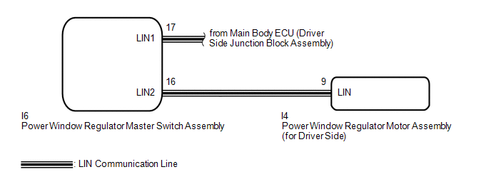
WIRING DIAGRAM
CAUTION / NOTICE / HINT
NOTICE:
- The power window control system uses a multiplex communication system
(LIN communication system). Inspect the communication function by following
How to Proceed with Troubleshooting (See page
). Troubleshoot the power window control
system after confirming that the communication system is functioning properly. - When the power window regulator motor assembly (for driver side) is reinstalled or replaced, the power window control system must be initialized.
- After a door glass or a door glass run has been replaced, the jam protection
function may operate unexpectedly when the auto up function is used. In
such cases, the auto up function can be reinitialized by repeating the following
operations at least 5 times:
- Close the power window by fully pulling up the power window regulator master switch assembly and holding it at the auto up position.
- Open the power window by fully pushing down the power window regulator master switch assembly.
- When the ECU determines that the power window regulator motor assembly (for driver side) has a malfunction, DTC B2311 is set.
PROCEDURE
|
1. |
READ VALUE USING TECHSTREAM (Master Switch) |
(a) Connect the Techstream to the DLC3.
(b) Turn the ignition switch to ON.
(c) Turn the Techstream on.
(d) Enter the following menus: Body Electrical / Master switch / Data List.
(e) Read the Data List according to the display on the Techstream.
Master Switch (Power Window Regulator Master Switch Assembly)|
Tester Display |
Measurement Item/Range |
Normal Condition |
Diagnostic Note |
|---|---|---|---|
|
D Door P/W Auto SW |
Driver side power window auto up/down switch signal / ON or OFF |
ON: Driver side power window auto switch operated OFF: Driver side power window auto switch not operated |
- |
OK:
On the Techstream screen, ON or OFF is displayed accordingly.
| NG | .gif) |
REPLACE POWER WINDOW REGULATOR MASTER SWITCH ASSEMBLY |
|
.gif)
|
2. |
READ VALUE USING TECHSTREAM (D-Door Motor) |
(a) Enter the following menus: Body Electrical / D-Door Motor / Data List.
(b) Read the Data List according to the display on the Techstream.
D-Door Motor (Power Window Regulator Motor Assembly (for Driver Side))|
Tester Display |
Measurement Item/Range |
Normal Condition |
Diagnostic Note |
|---|---|---|---|
|
D Door P/W Auto SW |
Driver side power window auto up/down switch signal / ON or OFF |
ON: Driver side power window auto switch operated OFF: Driver side power window auto switch not operated |
- |
OK:
On the Techstream screen, ON or OFF is displayed accordingly.
| NG | |
GO TO STEP 5 |
|
|
3. |
PERFORM INITIALIZATION (for Driver Side) |
(a) Initialize the power window regulator motor assembly (for driver side) (See
page ).
|
|
4. |
CHECK POWER WINDOW CONTROL SYSTEM (AUTO UP/DOWN FUNCTION) |
(a) Check that the driver side door power window moves when the auto up/down
function of the power window regulator master switch assembly is operated (See page
).
OK:
Driver side auto up/down function is normal.
| OK | |
END (PROBLEM DUE TO INITIALIZATION FAILURE) |
| NG | |
REPLACE POWER WINDOW REGULATOR MOTOR ASSEMBLY (for Driver Side) |
|
5. |
REPLACE POWER WINDOW REGULATOR MASTER SWITCH ASSEMBLY |
(a) Replace the power window regulator master switch assembly (See page
).
|
|
6. |
CHECK POWER WINDOW CONTROL SYSTEM (AUTO UP/DOWN FUNCTION) |
(a) Check that the driver side door power window moves when the auto up/down
function of the power window regulator master switch assembly is operated (See page
).
OK:
Driver side auto up/down function is normal.
| OK | |
END (POWER WINDOW REGULATOR MASTER SWITCH WAS DEFECTIVE) |
| NG | |
REPLACE POWER WINDOW REGULATOR MOTOR ASSEMBLY (for Driver Side) |
 Rear Power Window RH does not Operate with Rear Power Window Switch RH
DESCRIPTION
When the engine is running or the ignition switch is ON, the power window regulator
motor assembly (for rear RH side) is operated by the power window regulator switch
assembly (for re ...
 Front Passenger Side Power Window Auto Up / Down Function does not Operate with
Front Passenger Side Power Window Switch
Front Passenger Side Power Window Auto Up / Down Function does not Operate with
Front Passenger Side Power Window Switch
DESCRIPTION
If the manual up/down function can be performed but the auto up/down function
cannot, the fail-safe mode may be functioning.
If the power window initialization (See page
) has not be ...
Other materials about Toyota Venza:
Reassembly
REASSEMBLY
PROCEDURE
1. INSTALL NO. 1 INSTRUMENT PANEL PIN
(a) Install the 2 No. 1 instrument panel pins with the 2 screws <E> or
<F>.
2. INSTALL GLOVE BOX LIGHT ASSEMBLY
...
Yaw Rate Sensor Output Malfunction (C1448/98)
DESCRIPTION
The skid control ECU receives signals from the yaw rate and acceleration sensor
via the CAN communication system.
The yaw rate sensor has a built-in acceleration sensor and detects the vehicle
condition.
DTC Code
DTC De ...
Installation
INSTALLATION
PROCEDURE
1. INSTALL DRIVER SIDE KNEE AIRBAG ASSEMBLY
(a) Check that the ignition switch is off.
(b) Check that the cable is disconnected from the negative (-) battery terminal.
CAUTION:
Wait at least 90 seconds after disconnecting the cable ...

0.1608