Toyota Venza: Rear Occupant Classification Sensor RH Circuit Malfunction (B1783)
DESCRIPTION
The rear occupant classification sensor RH circuit consists of the occupant classification ECU and rear occupant classification sensor RH.
DTC B1783 is recorded when a malfunction is detected in the rear occupant classification sensor RH circuit.
|
DTC No. |
DTC Detecting Condition |
Trouble Area |
|---|---|---|
|
B1783 |
|
|
HINT:
When DTC B1650/32 is detected as a result of troubleshooting for the airbag system, check the DTCs stored in the occupant classification ECU. When DTC B1783 is output, perform troubleshooting for the DTC.
WIRING DIAGRAM
.png)
CAUTION / NOTICE / HINT
HINT:
- If troubleshooting (wire harness inspection) is difficult to perform, remove the front passenger seat installation bolts to see under the seat cushion.
- In the above case, hold the seat so that it does not fall down. Hold the seat only as necessary because holding the seat for a long period of time may cause seat rail deformation.
PROCEDURE
|
1. |
CHECK CONNECTORS |
(a) Turn the ignition switch off.
(b) Disconnect the cable from the negative (-) battery terminal.
(c) Check that the connectors are properly connected to occupant classification ECU and the rear occupant classification sensor RH.
OK:
The connectors are properly connected.
HINT:
If the connectors are not connected securely, reconnect the connectors and proceed to the next inspection.
(d) Disconnect the connectors from the occupant classification ECU and rear occupant classification sensor RH.
(e) Check that the terminals of connectors are not damaged.
OK:
The terminals are not deformed or damaged.
| NG | .gif) |
REPLACE FRONT SEAT WIRE RH |
|
.gif)
|
2. |
CHECK FRONT SEAT WIRE RH (SHORT TO B+) |
|
(a) Connect the cable to the negative (-) battery terminal. |
|
(b) Turn the ignition switch to ON.
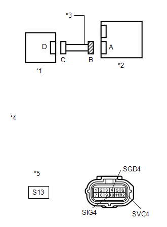
(c) Measure the voltage according to the value(s) in the table below.
Standard Voltage:
|
Tester Connection |
Switch Condition |
Specified Condition |
|---|---|---|
|
S13-4 (SGD4) - Body ground |
Ignition switch ON |
Below 1 V |
|
S13-6 (SVC4) - Body ground |
Ignition switch ON |
Below 1 V |
|
S13-10 (SIG4) - Body ground |
Ignition switch ON |
Below 1 V |
|
*1 |
Rear Occupant Classification Sensor RH |
|
*2 |
Occupant Classification ECU |
|
*3 |
Front Seat Wire RH |
|
*4 |
Front view of wire harness connector (to Occupant Classification ECU) |
|
*5 |
Connector B |
| NG | |
REPLACE FRONT SEAT WIRE RH |
|
|
3. |
CHECK FRONT SEAT WIRE RH (OPEN) |
(a) Turn the ignition switch off.
(b) Disconnect the cable from the negative (-) battery terminal.
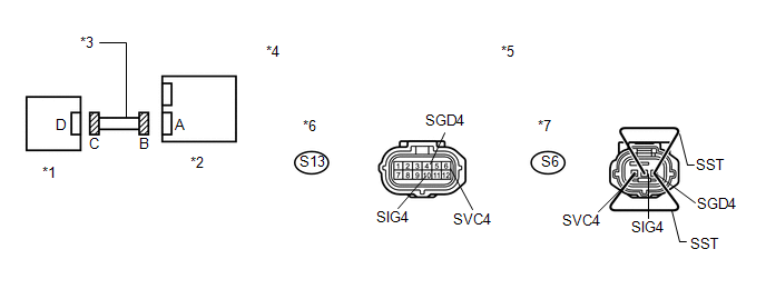
(c) Using SST, connect terminals 1 (SVC4) and 3 (SGD4), and connect terminals 2 (SIG4) and 3 (SGD4) of connector C.
NOTICE:
Do not forcibly insert SST into the terminals of the connector when connecting.
SST: 09843-18040
(d) Measure the resistance according to the value(s) in the table below.
Standard Resistance:
|
Tester Connection |
Condition |
Specified Condition |
|---|---|---|
|
S13-6 (SVC4) - S13-4 (SGD4) |
Always |
Below 1 Ω |
|
S13-10 (SIG4) - S13-4 (SGD4) |
Always |
Below 1 Ω |
|
*1 |
Rear Occupant Classification Sensor RH |
*2 |
Occupant Classification ECU |
|
*3 |
Front Seat Wire RH |
*4 |
Front view of wire harness connector (to Occupant Classification ECU) |
|
*5 |
Front view of wire harness connector (to Rear Occupant Classification Sensor RH) |
*6 |
Connector B |
|
*7 |
Connector C |
- |
- |
| NG | |
REPLACE FRONT SEAT WIRE RH |
|
|
4. |
CHECK FRONT SEAT WIRE RH (SHORT) |
|
(a) Disconnect SST from connector C. |
|
(b) Measure the resistance according to the value(s) in the table below.
Standard Resistance:
|
Tester Connection |
Condition |
Specified Condition |
|---|---|---|
|
S13-6 (SVC4) - S13-4 (SGD4) |
Always |
1 MΩ or higher |
|
S13-10 (SIG4) - S13-4 (SGD4) |
Always |
1 MΩ or higher |
|
S13-6 (SVC4) - S13-10 (SIG4) |
Always |
1 MΩ or higher |
|
*1 |
Rear Occupant Classification Sensor RH |
|
*2 |
Occupant Classification ECU |
|
*3 |
Front Seat Wire RH |
|
*4 |
Front view of wire harness connector (to Occupant Classification ECU) |
|
*5 |
Connector B |
| NG | |
REPLACE FRONT SEAT WIRE RH |
|
|
5. |
CHECK FRONT SEAT WIRE RH (SHORT TO GROUND) |
|
(a) Measure the resistance according to the value(s) in the table below. Standard Resistance:
|
|
| NG | |
REPLACE FRONT SEAT WIRE RH |
|
|
6. |
CHECK DTC |
(a) Connect the connectors to the occupant classification ECU and rear occupant classification sensor RH.
(b) Connect the cable to the negative (-) battery terminal.
(c) Turn the ignition switch to ON.
(d) Clear the DTCs stored in the occupant classification ECU (See page
.gif) ).
).
(e) Clear the DTCs stored in the center airbag sensor assembly (See page
).
(f) Turn the ignition switch off.
(g) Turn the ignition switch to ON.
(h) Check for DTCs (See page ).
OK:
DTC B1783 is not output.
HINT:
Codes other than DTC B1783 may be output at this time, but they are not related to this check.
| OK | |
USE SIMULATION METHOD TO CHECK |
|
|
7. |
REPLACE OCCUPANT CLASSIFICATION ECU |
(a) Turn the ignition switch off.
(b) Disconnect the cable from the negative (-) battery terminal.
(c) Replace the occupant classification ECU (See page
).
HINT:
Perform the inspection using parts from a normal vehicle if possible.
|
|
8. |
PERFORM ZERO POINT CALIBRATION |
(a) Connect the cable to the negative (-) battery terminal.
(b) Connect the Techstream to the DLC3.
(c) Turn the ignition switch to ON.
(d) Using the Techstream, perform Zero Point Calibration (See page
).
OK:
"Zero Point Calibration is complete." is displayed.
| NG | |
GO TO STEP 11 |
|
|
9. |
PERFORM SENSITIVITY CHECK |
(a) Using the Techstream, perform Sensitivity Check (See page
).
Standard:
27 to 33 kg (59.5 to 72.8 lb)
| NG | |
GO TO STEP 11 |
|
|
10. |
CHECK DTC |
(a) Turn the ignition switch to ON.
(b) Clear the DTCs stored in the occupant classification ECU (See page
).
(c) Clear the DTCs stored in the center airbag sensor assembly (See page
).
(d) Turn the ignition switch off.
(e) Turn the ignition switch to ON.
(f) Check for DTCs (See page ).
OK:
DTC B1783 is not output.
HINT:
Codes other than DTC B1783 may be output at this time, but they are not related to this check.
| OK | |
END |
|
|
11. |
REPLACE FRONT SEAT FRAME WITH ADJUSTER ASSEMBLY RH |
(a) Turn the ignition switch off.
(b) Disconnect the cable from the negative (-) battery terminal.
(c) Replace the front seat frame with adjuster assembly RH (See page
for power seat or
for manual seat).
|
|
12. |
PERFORM ZERO POINT CALIBRATION |
(a) Connect the cable to the negative (-) battery terminal.
(b) Connect the Techstream to the DLC3.
(c) Turn the ignition switch to ON.
(d) Using the Techstream, perform Zero Point Calibration (See page
).
OK:
"Zero Point Calibration is complete." is displayed.
|
|
13. |
PERFORM SENSITIVITY CHECK |
(a) Using the Techstream, perform Sensitivity Check (See page
).
Standard:
27 to 33 kg (59.5 to 72.8 lb)
| NEXT | |
END |
 Rear Occupant Classification Sensor LH Circuit Malfunction (B1782)
DESCRIPTION
The rear occupant classification sensor LH circuit consists of the occupant classification
ECU and rear occupant classification sensor LH.
DTC B1782 is recorded when a malfunction is d ...
 Front Occupant Classification Sensor RH Circuit Malfunction (B1781)
DESCRIPTION
The front occupant classification sensor RH circuit consists of the occupant
classification ECU and front occupant classification sensor RH.
DTC B1781 is recorded when a malfunction is ...
Other materials about Toyota Venza:
Installation
INSTALLATION
PROCEDURE
1. TEMPORARILY TIGHTEN COMPRESSOR AND MAGNETIC CLUTCH
(a) Temporarily install the compressor and magnetic clutch and bracket
with the 4 bolts.
2. INSTALL COMPRESSOR AND MA ...
Lost Communication with Automatic High Beam Sensor (B2432)
DESCRIPTION
Refer to DTC B2432 (Lighting system) (See page
).
DTC No.
DTC Detection Condition
Trouble Area
B2432
Malfunction in LIN communication system
Inner rear view mirr ...
Door Control Transmitter(w/ Smart Key System)
Components
COMPONENTS
ILLUSTRATION
Removal
REMOVAL
PROCEDURE
1. REMOVE TRANSMITTER BATTERY
Inspection
INSPECTION
PROCEDURE
1. INSPECT DOOR CONTROL TRANSMITTER
(a) Inspect operation of the transmitter.
(1) Remove the battery (lithium batt ...

0.1705