Toyota Venza: Installation
INSTALLATION
PROCEDURE
1. TEMPORARILY TIGHTEN COMPRESSOR AND MAGNETIC CLUTCH
|
(a) Temporarily install the compressor and magnetic clutch and bracket with the 4 bolts. |
|
.png)
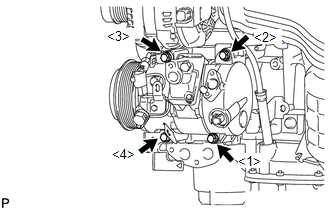
2. INSTALL COMPRESSOR AND MAGNETIC CLUTCH
|
(a) Install the compressor and magnetic clutch and bracket with the 4 bolts. Torque: 25 N·m {255 kgf·cm, 18 ft·lbf} NOTICE: Tighten the bolts in the order shown in the illustration to install the compressor and magnetic clutch. |
|
|
(b) Engage each clamp. |
|
.png)
(c) Connect each connector.
3. CONNECT SUCTION HOSE SUB-ASSEMBLY
(a) Remove the attached vinyl tape from the hose.
(b) Apply sufficient compressor oil to a new O-ring and the fitting surface of the compressor and magnetic clutch.
Compressor oil:
ND-OIL 8 or equivalent
(c) Install the O-ring onto the suction hose sub-assembly.
NOTICE:
Keep the O-ring and O-ring fitting surfaces free from dirt or any foreign objects.
|
(d) Install the suction hose sub-assembly onto the compressor and magnetic clutch with the bolt. Torque: 9.8 N·m {100 kgf·cm, 87 in·lbf} |
|
.png)
4. CONNECT COOLER REFRIGERANT DISCHARGE HOSE
(a) Remove the attached vinyl tape from the hose.
(b) Apply sufficient compressor oil to a new O-ring and the fitting surface of the compressor and magnetic clutch.
Compressor oil:
ND-OIL 8 or equivalent
(c) Install the O-ring onto the discharge hose.
NOTICE:
Keep the O-ring and O-ring fitting surfaces free from dirt or any foreign objects.
|
(d) Install the cooler refrigerant discharge hose onto the compressor and magnetic clutch with the bolt. Torque: 9.8 N·m {100 kgf·cm, 87 in·lbf} |
|
.png)
5. INSTALL RADIATOR ASSEMBLY AND FAN ASSEMBLY WITH MOTOR
.gif)
6. INSTALL COOLER CONDENSER ASSEMBLY
7. CONNECT AIR CONDITIONING TUBE AND ACCESSORY ASSEMBLY
8. CONNECT COOLER REFRIGERANT DISCHARGE HOSE
9. INSTALL UPPER RADIATOR SUPPORT
10. CONNECT OUTLET OIL COOLER HOSE
11. CONNECT INLET OIL COOLER HOSE
12. INSTALL NO. 2 RADIATOR HOSE
13. CONNECT NO. 1 RADIATOR HOSE
14. CONNECT OUTLET RESERVE TANK HOSE
15. INSTALL HOOD LOCK SUPPORT SUB-ASSEMBLY
16. INSTALL HOOD LOCK ASSEMBLY (w/o Engine Hood Courtesy Switch)
17. INSTALL HOOD LOCK ASSEMBLY (w/ Engine Hood Courtesy Switch)
18. INSTALL LOW PITCHED HORN ASSEMBLY
19. INSTALL HIGH PITCHED HORN ASSEMBLY
20. INSTALL INLET NO. 1 AIR CLEANER
21. INSTALL BATTERY
22. INSTALL AIR CLEANER CASE
23. INSTALL AIR CLEANER CAP WITH HOSE
24. INSTALL INLET NO. 2 AIR CLEANER
25. INSTALL RADIATOR GRILLE
26. INSTALL V-RIBBED BELT
27. INSTALL FRONT FENDER APRON RH
28. INSTALL FRONT FENDER LINER RH
29. INSTALL FRONT WHEEL RH
30. ADD ENGINE COOLANT
31. ADD AUTOMATIC TRANSAXLE FLUID
for U660F: (See page )
for U660E: (See page )
32. CONNECT CABLE TO NEGATIVE BATTERY TERMINAL
NOTICE:
When disconnecting the cable, some systems need to be initialized after the cable
is reconnected (See page ).
33. CHARGE WITH REFRIGERANT
34. WARM UP ENGINE
35. INSPECT FOR REFRIGERANT LEAK
36. INSPECT FOR COOLANT LEAK
37. INSTALL V-BANK COVER SUB-ASSEMBLY
38. INSTALL COOL AIR INTAKE DUCT SEAL
39. INSTALL NO. 2 ENGINE UNDER COVER
40. INSTALL NO. 1 ENGINE UNDER COVER
41. INSPECT HOOD SUB-ASSEMBLY
42. ADJUST HOOD SUB-ASSEMBLY
 Inspection
INSPECTION
PROCEDURE
1. INSPECT COMPRESSOR AND MAGNETIC CLUTCH (A/C LOCK SENSOR)
(a) Measure the resistance according to the value(s) in the table below.
Standard Resistance:
...
 Reassembly
REASSEMBLY
PROCEDURE
1. INSTALL MAGNETIC CLUTCH ASSEMBLY
(a) Install the magnetic clutch stator while aligning the protrusion
on the stator with the notch on the air compressor assem ...
Other materials about Toyota Venza:
Pressure Control Solenoid "A" Performance (Shift Solenoid Valve SL1) (P0746)
SYSTEM DESCRIPTION
The TCM uses the vehicle speed signal and signals from the transmission speed
sensors (NC, NT) to detect the actual gear (1st, 2nd, 3rd, 4th, 5th or 6th gear).
Then the TCM compares the actual gear with the shift schedule in the TCM memo ...
Radio Receiver Power Source Circuit
DESCRIPTION
This is the power source circuit to operate the radio and display receiver assembly.
WIRING DIAGRAM
CAUTION / NOTICE / HINT
NOTICE:
Inspect the fuses for circuits related to this system before performing the following
inspection procedure. ...
Speaker Circuit
DESCRIPTION
If there is a short in a speaker circuit, the radio and display receiver
assembly detects it and stops output to the speakers.
Thus sound cannot be heard from the speakers even if there is no malfunction
in the radio and display ...

0.1291