Toyota Venza: Front Occupant Classification Sensor RH Circuit Malfunction (B1781)
DESCRIPTION
The front occupant classification sensor RH circuit consists of the occupant classification ECU and front occupant classification sensor RH.
DTC B1781 is recorded when a malfunction is detected in the front occupant classification sensor RH circuit.
|
DTC No. |
DTC Detection Condition |
Trouble Area |
|---|---|---|
|
B1781 |
|
|
HINT:
When DTC B1650/32 is detected as a result of troubleshooting for the airbag system, check the DTCs stored in the occupant classification ECU. When DTC B1781 is output, perform troubleshooting for the DTC.
WIRING DIAGRAM
.png)
CAUTION / NOTICE / HINT
HINT:
- If troubleshooting (wire harness inspection) is difficult to perform, remove the front passenger seat installation bolts to see under the seat cushion.
- In the above case, hold the seat so that it does not fall down. Hold the seat only as necessary because holding the seat for a long period of time may cause seat rail deformation.
PROCEDURE
|
1. |
CHECK CONNECTORS |
(a) Turn the ignition switch off.
(b) Disconnect the cable from the negative (-) battery terminal.
(c) Check that the connectors are properly connected to the occupant classification ECU and front occupant classification sensor RH.
OK:
The connectors are properly connected.
HINT:
If the connectors are not connected securely, reconnect the connectors and proceed to the next inspection.
(d) Disconnect the connectors from the occupant classification ECU and front occupant classification sensor RH.
(e) Check that the terminals of connectors are not damaged.
OK:
The terminals are not deformed or damaged.
| NG | .gif) |
REPLACE FRONT SEAT WIRE RH |
|
.gif)
|
2. |
CHECK FRONT SEAT WIRE RH (SHORT TO B+) |
|
(a) Connect the cable to the negative (-) battery terminal. |
|
(b) Turn the ignition switch to ON.
(c) Measure the voltage according to the value(s) in the table below.
Standard Voltage:
|
Tester Connection |
Switch Condition |
Specified Condition |
|---|---|---|
|
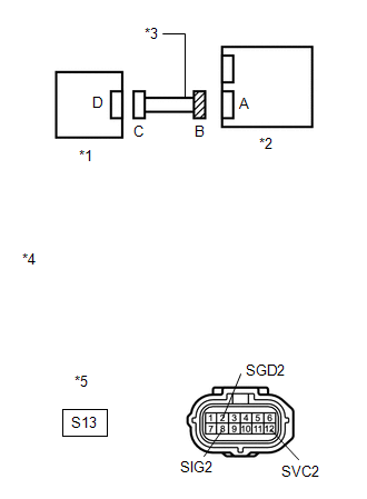
S13-2 (SGD2) - Body ground |
Ignition switch ON |
Below 1 V |
|
S13-8 (SIG2) - Body ground |
Ignition switch ON |
Below 1 V |
|
S13-12 (SVC2) - Body ground |
Ignition switch ON |
Below 1 V |
|
*1 |
Front Occupant Classification Sensor RH |
|
*2 |
Occupant Classification ECU |
|
*3 |
Front Seat Wire RH |
|
*4 |
Front view of wire harness connector (to Occupant Classification ECU) |
|
*5 |
Connector B |
| NG | |
REPLACE FRONT SEAT WIRE RH |
|
|
3. |
CHECK FRONT SEAT WIRE RH (OPEN) |
(a) Turn the ignition switch off.
(b) Disconnect the cable from the negative (-) battery terminal.
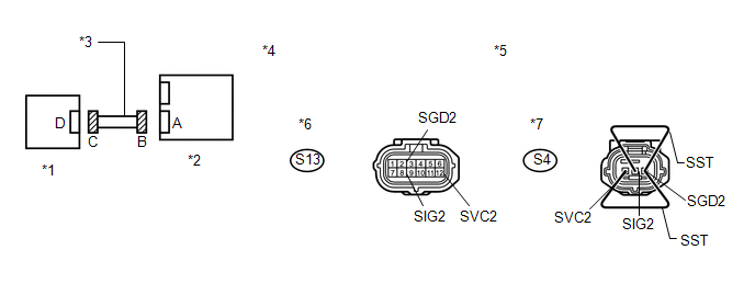
(c) Using SST, connect terminals 1 (SVC2) and 3 (SGD2), and connect terminals 2 (SIG2) and 3 (SGD2) of connector C.
NOTICE:
Do not forcibly insert SST into the terminals of the connector when connecting.
SST: 09843-18040
(d) Measure the resistance according to the value(s) in the table below.
Standard Resistance:
|
Tester Connection |
Condition |
Specified Condition |
|---|---|---|
|
S13-8 (SIG2) - S13-2 (SGD2) |
Always |
Below 1 Ω |
|
S13-12 (SVC2) - S13-2 (SGD2) |
Always |
Below 1 Ω |
|
*1 |
Front Occupant Classification Sensor RH |
*2 |
Occupant Classification ECU |
|
*3 |
Front Seat Wire RH |
*4 |
Front view of wire harness connector (to Occupant Classification ECU) |
|
*5 |
Front view of wire harness connector (to Front Occupant Classification Sensor RH) |
*6 |
Connector B |
|
*7 |
Connector C |
- |
- |
| NG | |
REPLACE FRONT SEAT WIRE RH |
|
|
4. |
CHECK FRONT SEAT WIRE RH (SHORT) |
|
(a) Disconnect SST from connector C. |
|
(b) Measure the resistance according to the value(s) in the table below.
Standard Resistance:
|
Tester Connection |
Condition |
Specified Condition |
|---|---|---|
|
S13-8 (SIG2) - S13-2 (SGD2) |
Always |
1 MΩ or higher |
|
S13-12 (SVC2) - S13-2 (SGD2) |
Always |
1 MΩ or higher |
|
S13-8 (SIG2) - S13-12 (SVC2) |
Always |
1 MΩ or higher |
|
*1 |
Front Occupant Classification Sensor RH |
|
*2 |
Occupant Classification ECU |
|
*3 |
Front Seat Wire RH |
|
*4 |
Front view of wire harness connector (to Occupant Classification ECU) |
|
*5 |
Connector B |
| NG | |
REPLACE FRONT SEAT WIRE RH |
|
|
5. |
CHECK FRONT SEAT WIRE RH (SHORT TO GROUND) |
|
(a) Measure the resistance according to the value(s) in the table below. Standard Resistance:
|
|
| NG | |
REPLACE FRONT SEAT WIRE RH |
|
|
6. |
CHECK DTC |
(a) Connect the connectors to the occupant classification ECU and the front occupant classification sensor RH.
(b) Connect the cable to the negative (-) battery terminal.
(c) Turn the ignition switch to ON.
(d) Clear the DTCs stored in the occupant classification ECU (See page
.gif) ).
).
(e) Clear the DTCs stored in the center airbag sensor assembly (See page
).
(f) Turn the ignition switch off.
(g) Turn the ignition switch to ON.
(h) Check for DTCs (See page ).
OK:
DTC B1781 is not output.
HINT:
Codes other than DTC B1781 may be output at this time, but they are not related to this check.
| OK | |
USE SIMULATION METHOD TO CHECK |
|
|
7. |
REPLACE OCCUPANT CLASSIFICATION ECU |
(a) Turn the ignition switch off.
(b) Disconnect the cable from the negative (-) battery terminal.
(c) Replace the occupant classification ECU (See page
).
HINT:
Perform the inspection using parts from a normal vehicle if possible.
|
|
8. |
PERFORM ZERO POINT CALIBRATION |
(a) Connect the cable to the negative (-) battery terminal.
(b) Connect the Techstream to the DLC3.
(c) Turn the ignition switch to ON.
(d) Using the Techstream, perform Zero Point Calibration (See page
).
OK:
"Zero Point Calibration is complete." is displayed.
| NG | |
GO TO STEP 11 |
|
|
9. |
PERFORM SENSITIVITY CHECK |
(a) Using the Techstream, perform Sensitivity Check (See page
).
Standard:
27 to 33 kg (59.5 to 72.8 lb)
| NG | |
GO TO STEP 11 |
|
|
10. |
CHECK DTC |
(a) Turn the ignition switch to ON.
(b) Clear the DTCs stored in the occupant classification ECU (See page
).
(c) Clear the DTCs stored in the center airbag sensor assembly (See page
).
(d) Turn the ignition switch off.
(e) Turn the ignition switch to ON.
(f) Check for DTCs (See page ).
OK:
DTC B1781 is not output.
HINT:
Codes other than DTC B1781 may be output at this time, but they are not related to this check.
| OK | |
END |
|
|
11. |
REPLACE FRONT SEAT FRAME WITH ADJUSTER ASSEMBLY RH |
(a) Turn the ignition switch off.
(b) Disconnect the cable from the negative (-) battery terminal.
(c) Replace the front seat frame with adjuster assembly RH (See page
for power seat or
for manual seat).
|
|
12. |
PERFORM ZERO POINT CALIBRATION |
(a) Connect the cable to the negative (-) battery terminal.
(b) Connect the Techstream to the DLC3.
(c) Turn the ignition switch to ON.
(d) Using the Techstream, perform Zero Point Calibration (See page
).
OK:
"Zero Point Calibration is complete." is displayed.
|
|
13. |
PERFORM SENSITIVITY CHECK |
(a) Using the Techstream, perform Sensitivity Check (See page
).
Standard:
27 to 33 kg (59.5 to 72.8 lb)
| NEXT | |
END |
 Rear Occupant Classification Sensor RH Circuit Malfunction (B1783)
DESCRIPTION
The rear occupant classification sensor RH circuit consists of the occupant classification
ECU and rear occupant classification sensor RH.
DTC B1783 is recorded when a malfunction is d ...
 Passenger Side Buckle Switch Circuit Malfunction (B1771)
DESCRIPTION
The passenger side buckle switch circuit consists of the occupant classification
ECU and front seat inner belt assembly RH.
DTC B1771 is recorded when a malfunction is detected in the ...
Other materials about Toyota Venza:
Rear Brake Flexible Hose
Components
COMPONENTS
ILLUSTRATION
Removal
REMOVAL
CAUTION / NOTICE / HINT
NOTICE:
If both the left and right side hoses are removed at the same time, be sure to
place identification marks indicating the position on each side.
HINT:
Us ...
Engine Coolant Temperature Circuit Range / Performance Problem (P0116)
DESCRIPTION
Refer to DTC P0115 (See page ).
DTC No.
DTC Detection Condition
Trouble Area
P0116
When either of the following conditions is met (2 trip detection logic).
During engine ...
Checking Monitor Status
CHECKING MONITOR STATUS
The purpose of the monitor result (mode 06) is to allow access to the results
of on-board diagnostic monitoring tests of specific components/systems that are
not continuously monitored. Examples are catalysts and evaporative emissi ...

0.1765