Toyota Venza: Performance Decline of Brake Function (C1441)
DESCRIPTION
The skid control ECU judges brake failure conditions have occurred based on the signal from the brake pedal load sensing switch and master cylinder pressure sensor.
NOTICE:
Do not intentionally stop the engine when driving. Even when no malfunction has occurred in the brake system, DTC C1441 will be stored when it is judged that a failure has occurred in the brake system due to a reduction in vacuum.
DTCs may be stored if one of the following occurs:
- The brake pedal load sensing switch is malfunctioning (deviation in characteristics).
- The brake pedal is depressed when moving the vehicle with the engine not running and the ignition switch to ON.
- Bleeding is performed with the engine running or the ignition switch to ON.
- Accelerator and brake pedals depressed simultaneously.*
HINT:
*: The skid control ECU may store this DTC upon judging that a stuck on malfunction has occurred when the accelerator pedal and brake pedal are depressed simultaneously. However, this does not indicate a malfunction.
|
DTC No. |
DTC Detection Condition |
Trouble Area |
|---|---|---|
|
C1441 |
When the brake pedal load sensing switch and master cylinder pressure sensor are functioning normally and the stop light switch and brake pedal load sensing switch are judged as on, the pressure signal from the master cylinder pressure sensor does not indicate an increase. |
|
PROCEDURE
|
1. |
CHECK ACCELERATOR PEDAL AND BRAKE PEDAL OPERATION |
(a) Interview the customer to check if the pedals were depressed simultaneously while driving or braking.
OK:
The pedals were not depressed simultaneously.
HINT:
The skid control ECU may store this DTC upon judging that a stuck on malfunction has occurred when the accelerator pedal and brake pedal are depressed simultaneously.
If the pedals were depressed simultaneously, clear the DTC because it is not a malfunction.
| NG | .gif) |
END |
|
.gif)
|
2. |
CHECK DTC AND FREEZE FRAME DATA |
(a) Check and record DTCs and Freeze Frame Data (See page
.gif) for DTC Check/Clear, or
for Freeze Frame Data).
for DTC Check/Clear, or
for Freeze Frame Data).
HINT:
Read Freeze Frame Data at the time DTC C1441 was stored, go to operation history and confirm the operating conditions.
When reading Freeze Frame Data to confirm operating conditions, the following items can be confirmed: "F# or R# Wheel Speed", "Vehicle Speed", "Real Engine Torque" and "Accelerator Opening Angle %".
|
|
3. |
CLEAR DTC |
(a) Clear the DTCs and Freeze Frame Data (See page
for DTC Check/Clear, or
for Freeze Frame Data).
|
|
4. |
CHECK BRAKE PEDAL OPERATION |
(a) Based on the customer problem analysis, confirm the brake pedal condition at the time the brake pedal was operated.
|
Result |
Proceed to |
|---|---|
|
The brake pedal is hard to depress. |
A |
|
The brake pedal is extremely easy to depress. |
B |
|
Neither of the above conditions. (Problem symptom does not occur.) |
C |
| B | |
GO TO STEP 6 |
| C | |
GO TO STEP 10 |
|
|
5. |
CHECK BRAKE BOOSTER ASSEMBLY |
(a) Check the brake booster assembly (See page
).
|
Result |
Proceed to |
|---|---|
|
The brake booster assembly is abnormal. |
A |
|
The brake booster assembly is normal. |
B |
HINT:
If the result shows that the brake booster assembly is defective, check the related components such as the brake booster, brake vacuum check valve, check valve grommet, brake booster gasket, vacuum hose and intake system for vacuum leaks or clogs.
| A | |
INSPECT RELATED COMPONENTS (FOR VACUUM LEAKS OR CLOGS) |
| B | |
GO TO STEP 10 |
|
6. |
INSPECT BRAKE SYSTEM |
(a) Brake pedal inspection
(1) Perform a visual inspection and operate the brake pedal to check for any malfunctions.
(2) Check the brake pedal height, brake pedal free play and brake pedal reserve distance.
Click here
HINT:
If the brake pedal height is not within specification, confirm that there are no other malfunctions before adjusting the brake pedal height.
(b) Brake inspection
(1) Check that the disc brake pads of each wheel are installed correctly.
(2) Check that the bleeder plug and union bolt is not loose, and that there are no damaged gaskets or brake fluid leaks, for each wheel cylinder.
(c) Brake fluid leaks and air in brake line inspection
(1) Check and take a note of the fluid level in the brake master cylinder reservoir assembly.
(2) Repeatedly depress the brake pedal and confirm that the brake pedal feels normal (no air in the system, etc.).
(3) Check if the brake fluid level in the brake master cylinder reservoir assembly has changed.
(4) If the brake fluid level has decreased, check for leaks due to damaged brake lines or hoses, loose union nuts, damaged brake master cylinder sub-assembly seals, etc.
(d) Bleeding air from brake system
(1) Bleed air from the brake lines and brake actuator assembly.
Click here
|
|
7. |
PERFORM ACTIVE TEST USING TECHSTREAM (ABS MOTOR RELAY) |
(a) Connect the Techstream to the DLC3.
(b) Turn the ignition switch to ON.
(c) Select the Active Test on the Techstream.
Click here
ABS/VSC/TRAC
|
Tester Display |
Test Part |
Control Range |
Diagnostic Note |
|---|---|---|---|
|
Motor Relay |
ABS motor relay |
Relay ON/OFF |
Operating sound of motor can be heard |
(d) Fully depress and hold the brake pedal.
HINT:
Make sure that the brake pedal has travelled excessively before holding it depressed.
(e) Operate the ABS motor relay using the Active Test and check if the brake pedal height changes when the pump motor is operating.
OK:
The brake pedal height does not change (the brake pedal travel remains excessive).
| NG | |
REPLACE BRAKE ACTUATOR ASSEMBLY |
|
|
8. |
CHECK BRAKE MASTER CYLINDER SUB-ASSEMBLY |
(a) Check that there are no brake fluid leaks and no indications of a malfunction in the brake master cylinder sub-assembly.
OK:
There are no brake fluid leaks and no indications of a malfunction in the brake master cylinder sub-assembly.
| NG | |
REPLACE BRAKE MASTER CYLINDER SUB-ASSEMBLY |
|
|
9. |
INSPECT BRAKE BOOSTER ASSEMBLY |
(a) Inspect operation of the brake booster assembly.
Click here
OK:
The brake booster assembly is normal.
| NG | |
REPLACE BRAKE BOOSTER ASSEMBLY |
|
|
10. |
RECONFIRM DTC |
(a) Clear the DTCs (See page ).
(b) Start the engine.
(c) Perform a road test.
NOTICE:
Do not intentionally stop the engine when driving. DTC C1441 will be stored if the brake pedal is depressed when moving the vehicle with the engine not running and the ignition switch to ON.
(d) Check if the same DTC is recorded (See page
).
|
Result |
Proceed to |
|---|---|
|
DTC C1441 is not output. |
A |
|
DTCs C1441 and other DTC are output. |
B |
|
Only DTC C1441 is output. |
C |
HINT:
If DTC C1441 and other DTCs are output simultaneously, the other DTCs may have caused the engine to malfunction, resulting in DTC C1441 to be output. Read Freeze Frame Data to confirm malfunctioning parts and repair the applicable part.
When reading Freeze Frame Data to confirm malfunctioning parts, the following items can be confirmed: "F# or R# Wheel Speed", "Vehicle Speed", "Real Engine Torque" and "Accelerator Opening Angle %".
| A | |
END |
| B | |
CHECK AND REPAIR APPLICABLE PART |
|
|
11. |
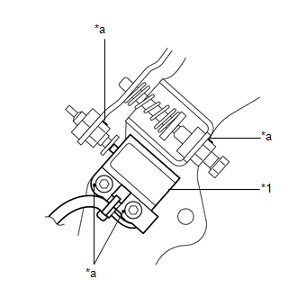
CHECK BRAKE PEDAL LOAD SENSING SWITCH |
|
(a) Check that the match marks on the adjustment part of the brake pedal load sensing switch are aligned with the match marks on the bracket, nut, adjusting screw, etc. Text in Illustration
OK: The match marks on the adjustment part of the brake pedal load sensing switch are aligned with the match marks on the bracket, nut, adjusting screw, etc. |
|
| OK | |
REPLACE BRAKE ACTUATOR ASSEMBLY |
| NG | |
REPLACE BRAKE PEDAL SUPPORT ASSEMBLY |
 Steering Angle Sensor Initialization Incomplete (C1439/31,C1445/31)
DESCRIPTION
The skid control ECU acquires the steering angle sensor zero point every time
the ignition switch is turned to ON and the vehicle is driven at 50 km/h (31 mph)
or more for approximate ...
 Yaw Rate Sensor Output Malfunction (C1448/98)
DESCRIPTION
The skid control ECU receives signals from the yaw rate and acceleration sensor
via the CAN communication system.
The yaw rate sensor has a built-in acceleration sensor and detects the ...
Other materials about Toyota Venza:
Short in Curtain Shield Squib LH Circuit (B1835/58-B1838/58)
DESCRIPTION
The curtain shield squib LH circuit consists of the center airbag sensor assembly
and curtain shield airbag assembly LH.
The center airbag sensor assembly uses this circuit to deploy the airbag when
deployment conditions are met.
These DTCs ...
Freeze Frame Data
FREEZE FRAME DATA
1. FREEZE FRAME DATA
(a) Whenever a DTC is detected, the AFS ECU (headlight swivel ECU assembly) stores
the current vehicle (sensor) state as Freeze Frame Data.
2. CHECK FREEZE FRAME DATA
(a) Connect the Techstream to the DLC3.
(b) Tur ...
Road Test
ROAD TEST
1. PROBLEM SYMPTOM CONFIRMATION
(a) Inspect the SET function.
Text in Illustration
*1
ON/OFF
*2
- SET
(1) Turn the cruise control main switch on.
(2) Drive at the required speed of bet ...

0.1523