Toyota Venza: Rear Axle Hub Bolt
Components
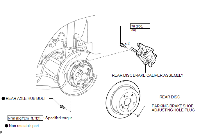
COMPONENTS
ILLUSTRATION
Replacement
REPLACEMENT
CAUTION / NOTICE / HINT
HINT:
- Use the same procedure for the RH side and LH side.
- The procedure listed below is for the LH side.
PROCEDURE
1. REMOVE REAR WHEEL
2. SEPARATE REAR DISC BRAKE CALIPER ASSEMBLY
.gif)
3. REMOVE REAR DISC
4. REMOVE REAR AXLE HUB BOLT
|
(a) Temporarily install the 2 nuts to the rear axle hub bolt as shown in the illustration. Text in Illustration
Recommended service nut: Thread diameter: 12.0 mm (0.472 in.) Thread pitch: 1.5 mm (0.0591 in.) NOTICE: Install the nuts to prevent damage to the rear axle hub bolts. |
|
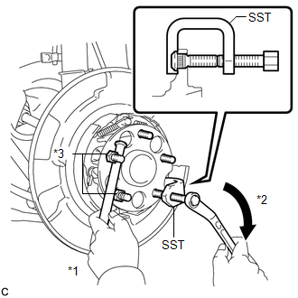
(b) Using SST and a brass bar or an equivalent tool to hold the rear axle hub and bearing assembly, remove the rear axle hub bolt.
SST: 09611-12010
NOTICE:
Do not damage the threads of the rear axle hub bolts.
5. INSTALL REAR AXLE HUB BOLT
|
(a) Temporarily install a new rear axle hub bolt to the rear axle hub and bearing assembly. |
|
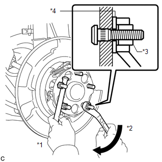
(b) Install a washer and nut to the new rear axle hub bolt as shown in the illustration.
Text in Illustration|
*1 |
Hold |
|
*2 |
Turn |
|
*3 |
Nut |
|
*4 |
Washer |
Recommended service nut:
Thread diameter: 12.0 mm (0.472 in.)
Thread pitch: 1.5 mm (0.0591 in.)
HINT:
The thickness of the washer is preferably 5 mm (0.197 in.) or more.
(c) Using a brass bar or an equivalent tool to hold the rear axle hub and bearing assembly, install the rear axle hub bolt by tightening the nut.
NOTICE:
- Install the nuts to prevent damage to the hub bolts.
- Do not damage the threads of the rear axle hub bolts.
(d) Remove the 3 nuts and washer from the 3 rear axle hub bolts.
6. INSTALL REAR DISC
7. INSTALL REAR DISC BRAKE CALIPER ASSEMBLY
8. INSTALL REAR WHEEL
Torque:
103 N·m {1050 kgf·cm, 76 ft·lbf}
 Installation
INSTALLATION
CAUTION / NOTICE / HINT
HINT:
Use the same procedure for the RH side and LH side.
The procedure listed below is for the LH side.
PROCEDURE
1. INSTALL REAR AXLE CARR ...

Other materials about Toyota Venza:
Oxygen (A/F) Sensor Heater Control Circuit Low (Bank 1 Sensor 1) (P0031,P0032,P101D)
DESCRIPTION
Refer to DTC P2195 (See page ).
HINT:
When any of these DTCs is stored, the ECM enters fail-safe mode. The
ECM turns off the air fuel ratio sensor heater in fail-safe mode. Fail-safe
mode continues until the ignition switch is t ...
Door Control Transmitter(w/o Smart Key System)
Components
COMPONENTS
ILLUSTRATION
Removal
REMOVAL
PROCEDURE
1. REMOVE TRANSMITTER HOUSING COVER
2. REMOVE DOOR CONTROL TRANSMITTER MODULE
Inspection
INSPECTION
PROCEDURE
1. INSPECT DOOR CONTROL TRANSMITTER
(a) Inspect operation of th ...
Installation
INSTALLATION
PROCEDURE
1. INSTALL FRONT SEAT ASSEMBLY
(a) Place the front seat assembly in the cabin.
NOTICE:
Be careful not to damage the vehicle body.
(b) Connect each connector under the front seat assembly.
(c) Temporarily install the front seat ass ...

0.1534