Toyota Venza: Parts Location
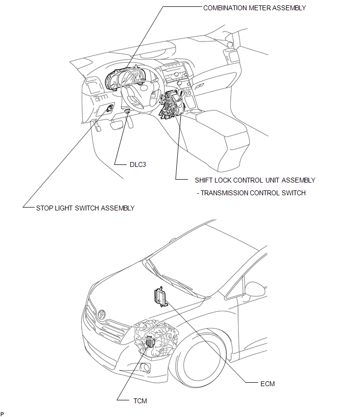
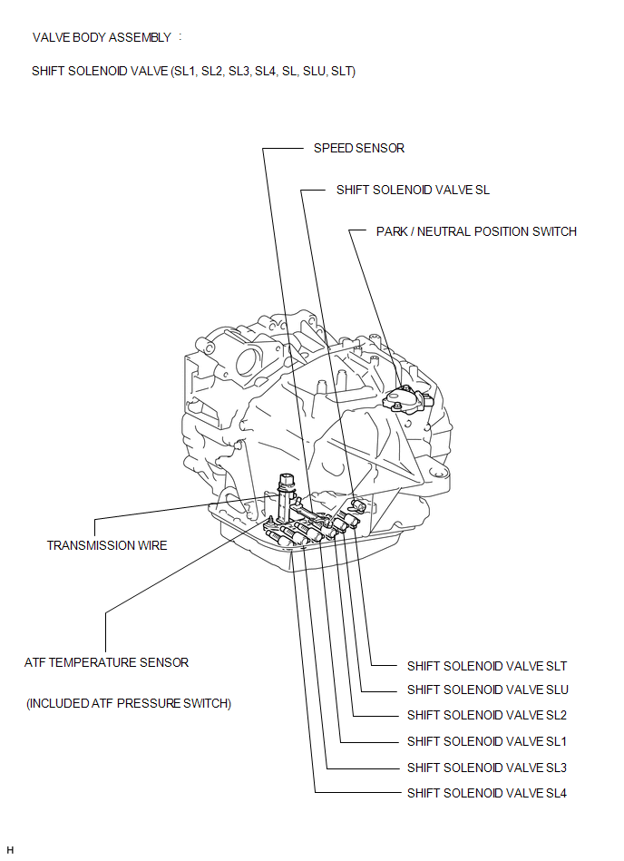
PARTS LOCATION
ILLUSTRATION
ILLUSTRATION
 Precaution
PRECAUTION
1. EXPRESSIONS OF IGNITION SWITCH
The type of ignition switch used on this model differs according to the specifications
of the vehicle.
The expressions listed in the table below are u ...
 System Description
SYSTEM DESCRIPTION
1. SYSTEM DESCRIPTION
(a) The Electronic Controlled Automatic Transaxle (ECT) is an automatic transaxle
that has its shift timing electronically controlled by the Transmission C ...
Other materials about Toyota Venza:
Disassembly
DISASSEMBLY
PROCEDURE
1. REMOVE STEERING RACK BOOT CLIP (for LH Side)
(a) Using pliers, remove the steering rack boot clip.
2. REMOVE STEERING RACK BOOT CLIP (for RH Side)
HINT:
Perform the same procedure as for the LH side.
3. REMOVE NO. 2 STEERING RAC ...
Wireless Door Lock Tuner Circuit Malfunction (B1242)
DESCRIPTION
The door control receiver receives signals from the transmitter and sends these
signals to the main body ECU (driver side junction block assembly).
DTC No.
DTC Detection Condition
Trouble Area
B ...
Fail-safe Chart
FAIL-SAFE CHART
1. Fail-safe
This function minimizes the loss of operation when any abnormality occurs in
a sensor or solenoid.
Fail-safe Control List
Malfunction Part
Function
Input Turbine Speed Sensor
...

0.2154