Toyota Venza: Engine Hood Courtesy Switch Circuit
DESCRIPTION
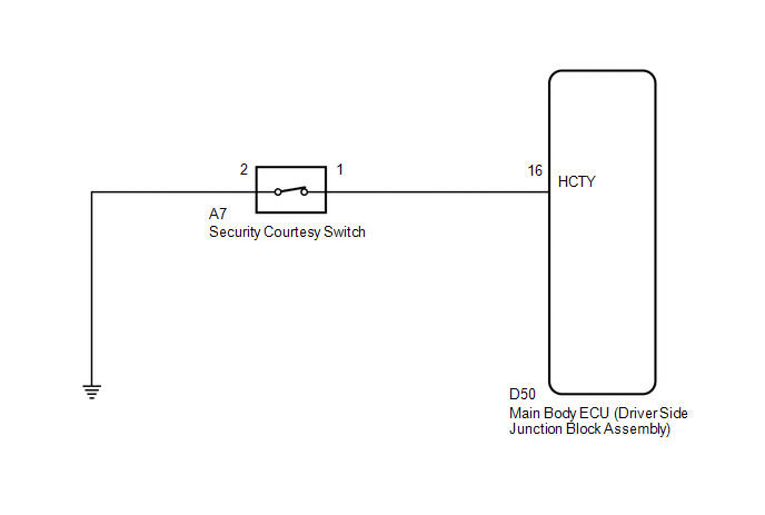
The security courtesy switch is installed together with the hood lock. This switch turns off when the engine hood is opened and turns on when the engine hood is closed.
WIRING DIAGRAM
PROCEDURE
|
1. |
INSPECT HOOD LOCK ASSEMBLY (SECURITY COURTESY SWITCH) |
|
(a) Remove the hood lock assembly (See page
|
|
.gif) ).
)..png)
(b) Disconnect the A7 security courtesy switch connector.
(c) Measure the resistance according to the value(s) in the table below.
Standard Resistance:
|
Tester Connection |
Switch Condition |
Specified Condition |
|---|---|---|
|
1 - 2 |
Opened |
Below 1 Ω |
|
Locked |
10 kΩ or higher |
|
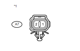
*1 |
Component without harness connected (Hood Lock Assembly (Security Courtesy Switch)) |
|
*2 |
Opened |
|
*3 |
Locked |
| NG | .gif) |
REPLACE HOOD LOCK ASSEMBLY (SECURITY COURTESY SWITCH) |
|
.gif)
|
2. |
CHECK HARNESS AND CONNECTOR (SECURITY COURTESY SWITCH - BODY GROUND) |
|
(a) Measure the resistance according to the value(s) in the table below. Standard Resistance:
|
|
| NG | |
REPAIR OR REPLACE HARNESS OR CONNECTOR |
|
|
3. |
CHECK HARNESS AND CONNECTOR (MAIN BODY ECU - SECURITY COURTESY SWITCH) |
|
(a) Disconnect the D50 main body ECU (driver side junction block assembly) connector. |
|
(b) Measure the resistance according to the value(s) in the table below.
Standard Resistance:
|
Tester Connection |
Condition |
Specified Condition |
|---|---|---|
|
D50-16 (HCTY) - A7-1 |
Always |
Below 1 Ω |
|
D50-16 (HCTY) - Body ground |
Always |
10 kΩ or higher |
|
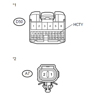
*1 |
Front view of wire harness connector (to Main Body ECU (Driver Side Junction Block Assembly)) |
|
*2 |
Front view of wire harness connector (to Security Courtesy Switch) |
| OK | |
PROCEED TO NEXT SUSPECTED AREA SHOWN IN PROBLEM SYMPTOMS TABLE |
| NG | |
REPAIR OR REPLACE HARNESS OR CONNECTOR |
 Diagnosis System
DIAGNOSIS SYSTEM
1. DESCRIPTION
The ECU stores trouble codes when trouble occurs on the vehicle.
The diagnostic system allows for reading of the trouble codes from the DLC3.
Use the Techstream to ...
 Horn Circuit
DESCRIPTION
When the theft deterrent system is switched from the armed state to the alarm
sounding state, the main body ECU (driver side junction block assembly) transmits
a signal to cause the h ...
Other materials about Toyota Venza:
How To Proceed With Troubleshooting
CAUTION / NOTICE / HINT
HINT:
Use the following procedure to troubleshoot the navigation system.
*: Use the Techstream.
PROCEDURE
1.
VEHICLE BROUGHT TO WORKSHOP
NEXT
...
All Doors LOCK/UNLOCK Functions do not Operate Via Door Control Switch
DESCRIPTION
The main body ECU (driver side junction block assembly) receives switch signals
from the door control switch and activates the door lock motor on each door according
to these signals.
WIRING DIAGRAM
PROCEDURE
1.
REA ...
Satellite Radio Broadcast cannot be Selected or After Selecting Broadcast, Broadcast
cannot be Added into Memory
CAUTION / NOTICE / HINT
NOTICE:
Some satellite radio broadcasts require payment. A contract must be made between
a satellite radio company and the user. If the contract expires, it will not be
possible to listen to the broadcast.
PROCEDURE
1 ...

0.1849