Toyota Venza: Diagnosis System
DIAGNOSIS SYSTEM
1. DESCRIPTION
The ECM controls the cruise control system of the vehicle. The data and DTCs relating to the cruise control system can be read from the DLC3 of the vehicle. If either DTC or CRUISE OK is not displayed on the multi-information display on the combination meter assembly when checking for DTCs, there may be a problem with either the combination meter assembly or the CAN communication system. Use the Techstream to check and solve the problem.
2. CHECK DLC3
(a) Check the DLC3 (See page .gif) ).
).
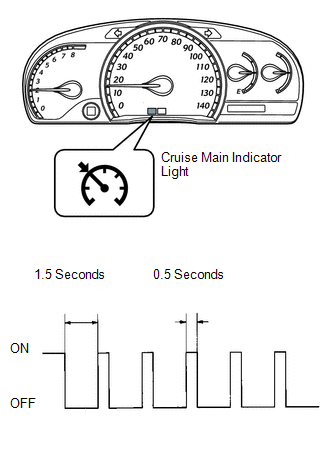
3. CHECK INDICATOR
(a) Turn the ignition switch to ON.
(b) Check that the CRUISE main indicator light illuminates when the cruise control
main switch is turned on, and that the indicator light turns off when the main switch
is turned off. If the results are not as specified, inspect the Cruise Main Indicator
Light Circuit (See page ).
HINT:
While driving with cruise control, the ECM activates AUTO CANCEL of the cruise control system when a malfunction occurs in one of the following: vehicle speed sensors, stop light switch assembly, or other related parts. When AUTO CANCEL is activated, the CRUISE main indicator light outputs the blinking pattern shown in the illustration. At the same time, data of the malfunction is stored as a DTC.
 Problem Symptoms Table
PROBLEM SYMPTOMS TABLE
HINT:
Use the table below to help determine the cause of problem symptoms.
If multiple suspected areas are listed, the potential causes of the symptoms
are lis ...
 Terminals Of Ecm
TERMINALS OF ECM
1. CHECK ECM
Terminal No. (Symbol)
Wiring Color
Terminal Description
Condition
Specified Condition
A49-7 (T ...
Other materials about Toyota Venza:
Engine Stall History (P1603,P1605)
DESCRIPTION
P1603
After starting the engine, this DTC is stored when the engine stops without the
ignition switch being operated.
Using the Techstream, the conditions present when the DTC was stored can be confirmed
by referring to the freeze frame data ...
Transmission Wire(when Using The Engine Support Bridge)
Components
COMPONENTS
ILLUSTRATION
Installation
INSTALLATION
PROCEDURE
1. INSTALL TRANSMISSION WIRE
(a) Coat the O-ring with ATF.
(b) Coat the bolt with ATF.
(c) Install the transmission ...
Illumination for Panel Switch does not Come on with Tail Switch ON
PROCEDURE
1.
CHECK VEHICLE SIGNAL (OPERATION CHECK)
(a) Enter the "Vehicle Signal Check Mode" screen.
Refer to Check Vehicle Signal in Operation Check (See page
).
...

0.1664