Toyota Venza: Terminals Of Ecu
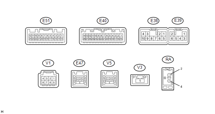
TERMINALS OF ECU
HINT:
Check from the rear of the connector while it is connected to the components.
1. NAVIGATION RECEIVER ASSEMBLY
|
Terminal No. (Symbol) |
Wiring Color |
Terminal Description |
Condition |
Specified Condition |
|---|---|---|---|---|
|
E38-1 (FR+) - E38-7 (GND1) |
LG - BR*1 R - BR*2 |
Sound signal (Front right)*1 Sound signal (Right)*2 |
Audio system playing |
A waveform synchronized with sound signals is output |
|
E38-2 (FL+) - E38-7 (GND1) |
P - BR*1 B - BR*2 |
Sound signal (Front left)*1 Sound signal (Left)*2 |
Audio system playing |
A waveform synchronized with sound signals is output |
|
E38-3 (ACC1) - E38-7 (GND1) |
GR - BR |
Power source (ACC) |
Ignition switch off |
Below 1 V |
|
Ignition switch ACC |
11 to 14 V |
|||
|
E38-4 (+B1) - E38-7 (GND1) |
SB - BR |
Power source (+B) |
Always |
11 to 14 V |
|
E38-5 (FR-) - E38-7 (GND1) |
L - BR*1 G - BR*2 |
Sound signal (Front right)*1 Sound signal (Right)*2 |
Audio system playing |
A waveform synchronized with sound signals is output |
|
E38-6 (FL-) - E38-7 (GND1) |
V - BR*1 W - BR*2 |
Sound signal (Front left)*1 Sound signal (Left)*2 |
Audio system playing |
A waveform synchronized with sound signals is output |
|
E38-7 (GND1) - Body ground |
BR - Body ground |
Ground |
Always |
Below 1 V |
|
E38-10 (ILL+) - E38-7 (GND1) |
G - BR |
Illumination signal |
Light control switch off |
Below 1 V |
|
Light control switch in tail or head position |
11 to 14 V |
|||
|
E39-1 (RR+) - E38-7 (GND1)*1 |
R - BR |
Sound signal (Rear right) |
Audio system playing |
A waveform synchronized with sound signals is output |
|
E39-2 (RL+) - E38-7 (GND1) |
B - BR*1 W - BR*2 |
Sound signal (Rear left)*1 Voice signal*2 |
Audio system playing*1 Voice guidance sounding*2 |
A waveform synchronized with sound signals is output*1 A waveform synchronized with voice signals is output*2 |
|
E39-3 (RR-) - E38-7 (GND1)*1 |
W - BR |
Sound signal (Rear right) |
Audio system playing |
A waveform synchronized with sound signals is output |
|
E39-5 (ILL-) - E38-7 (GND1) |
W - BR |
Illumination signal |
Light control switch off |
Below 1 V |
|
Light control switch in tail or head position |
Pulse generation |
|||
|
E39-6 (RL-) - E38-7 (GND1) |
Y - BR*1 B - BR*2 |
Sound signal (Rear left)*1 Voice signal*2 |
Audio system playing*1 Voice guidance sounding*2 |
A waveform synchronized with sound signals is output*1 A waveform synchronized with voice signals is output*2 |
|
E51-11 (CA+) - E38-7 (GND1) |
B - BR |
Television camera power supply |
Ignition switch ACC |
5.8 to 6.5 V |
|
E51-12 (V+) - E38-7 (GND1) |
R - BR |
Video signal |
Ignition switch ON Shift lever in R Camera lens not covered, displaying an image |
Pulse generation (Refer to waveform 1) |
|
Ignition switch ON Shift lever in R Camera lens covered, blacking out screen |
Pulse generation (Refer to waveform 2) |
|||
|
E51-23 (CGND) - Body ground |
Shield - Body ground |
Shield ground |
Always |
Below 1 V |
|
E51-24 (V-) - E38-7 (GND1) |
W - BR |
Ground |
Always |
Below 1 V |
|
E40-1 (IG) - E38-7 (GND1) |
V - BR |
Power source (IG) |
Ignition switch off |
Below 1 V |
|
Ignition switch ON |
11 to 14 V |
|||
|
E40-4 (MACC) - E38-7 (GND1) |
R - BR |
Microphone power supply |
Ignition switch off |
Below 1 V |
|
Ignition switch ACC |
4.75 to 5.25 V |
|||
|
E40-5 (MIN+) - E38-7 (GND1) |
B - BR |
Microphone voice signal |
See "Check Microphone" in Operation Check (See page
|
- |
|
E40-6 (SNS2) - E38-7 (GND1) |
Y - BR |
Microphone connection detection signal |
Always |
Below 1 V |
|
E40-7 (TX1+)*2 |
R |
AVC-LAN communication signal |
- |
- |
|
E40-8 (TX1-)*2 |
G |
AVC-LAN communication signal |
- |
- |
|
E40-9 (CANH) |
SB |
CAN communication signal |
- |
- |
|
E40-10 (CANL) |
W |
CAN communication signal |
- |
- |
|
E40-11 (AGND) - Body ground |
Shield - Body ground |
Shield ground |
Always |
Below 1 V |
|
E40-16 (MUT1) - E38-7 (GND1)*2 |
LG - BR |
Mute signal |
Ignition switch ACC Audio system playing |
2.0 V or higher |
|
Audio system changing modes |
Below 1 V |
|||
|
E40-17 (SPD) - E38-7 (GND1) |
BR - BR |
Vehicle speed signal |
See "Check Vehicle Signal" in Operation Check (See page
|
- |
|
E40-18 (SGND) - Body ground |
Shield - Body ground |
Shield ground |
Always |
Below 1 V |
|
E40-19 (MIN-) - E38-7 (GND1) |
W - BR |
Microphone voice signal |
See "Check Microphone" in Operation Check (See page
|
- |
|
E40-21 (SW1) - E40-23 (SWG) |
GR - R |
Steering pad switch signal |
No switch pushed |
2.97 to 3.56 V |
|
Up switch pushed |
0.27 to 0.35 V |
|||
|
Down switch pushed |
0.86 to 1.03 V |
|||
|
Volume+ switch pushed |
1.51 to 1.79 V |
|||
|
Volume- switch pushed |
2.22 to 2.66 V |
|||
|
E40-22 (SW2) - E40-23 (SWG) |
LG - R |
Steering pad switch signal |
No switch pushed |
2.97 to 3.56 V |
|
MODE/HOLD switch pushed |
0.27 to 0.35 V |
|||
|
On hook switch pushed |
0.86 to 1.03 V |
|||
|
Off hook switch pushed |
1.51 to 1.79 V |
|||
|
Voice switch pushed |
2.22 to 2.66 V |
|||
|
E40-23 (SWG) - E38-7 (GND1) |
R - BR |
Steering pad switch ground |
Always |
Below 1 V |
|
E40-24 (SW3) - E40-23 (SWG) |
L - R |
Steering pad switch signal |
No switch pushed |
2.97 to 3.56 V |
|
Enter switch pushed |
0.27 to 0.35 V |
|||
|
Back switch pushed |
0.86 to 1.03 V |
|||
|
Right switch pushed |
1.51 to 1.79 V |
|||
|
Left switch pushed |
2.22 to 2.66 V |
|||
|
E40-25 (ADPG) - E38-7 (GND1) |
SB - BR |
External device connection detection signal |
External device connected |
Below 1 V |
|
External device not connected |
2.1 to 3 V |
|||
|
E40-26 (VAR+) - E40-27 (VA-) |
R - W |
Sound signal (Right) |
External device playing (When stereo jack used) |
A waveform synchronized with sound signals is output |
|
E40-27 (VA-) - E38-7 (GND1) |
W - BR |
Ground |
Always |
Below 1 V |
|
E40-28 (VAL+) - E40-27 (VA-) |
B - W |
Sound signal (Left) |
External device system playing (when stereo jack used) |
A waveform synchronized with sound signals is output |
|
V1-3 (ACC2) - E38-7 (GND1)*3 |
Y - BR |
Power source (ACC) |
Ignition switch off |
Below 1 V |
|
Ignition switch ACC |
11 to 14 V |
|||
|
V1-4 (+B2) - E38-7 (GND1)*3 |
R - BR |
Power source (+B) |
Always |
11 to 14 V |
|
V1-8 (GND2) - Body ground*3 |
B - Body ground |
Ground |
Always |
Below 1 V |
|
E47-1 (USV1) |
- |
Power source |
- |
- |
|
E47-2 (US1-) |
- |
Data signal |
- |
- |
|
E47-3 (US1+) |
- |
Data signal |
- |
- |
|
E47-4 (UGD1) |
- |
Ground |
- |
- |
|
E47-5 (USG1) |
- |
Shield ground |
- |
- |
|
V5-1 (USV4)*3 |
- |
Power source |
- |
- |
|
V5-2 (US4-)*3 |
- |
Data signal |
- |
- |
|
V5-3 (US4+)*3 |
- |
Data signal |
- |
- |
|
V5-4 (UGD4)*3 |
- |
Ground |
- |
- |
|
V5-5 (USG4)*3 |
- |
Shield ground |
- |
- |
|
V3-1 (LV1)*3 |
B |
LVDS communication signal |
- |
- |
|
RA-5 (ANT+) - E38-7 (GND1) |
- - BR |
Power source of antenna |
Ignition switch ACC Radio switch on and FM or AM selected |
8.0 V or higher |
.gif) )
)- *1: for 6 Speakers
- *2: for 13 Speakers
- *3: w/ SDARS System
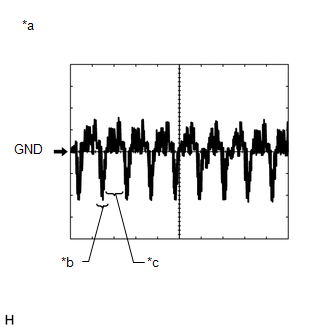
(a) Reference (Oscilloscope waveform):
(1) Waveform 1 (camera lens not covered, displaying an image)
|
Item |
Content |
|---|---|
|
Measurement terminal |
E51-12 (V+) - E38-7 (GND1) |
|
Measurement setting |
200 mV/DIV., 50 μs./DIV. |
|
Condition |
Ignition switch ON, shift lever in R |
HINT:
- The video waveform changes according to the image sent by the television camera assembly.
- The video waveform is constantly output when the ignition switch is turned to ACC.
|
*a |
Waveform 1 (camera lens not covered, displaying an image) |
|
*b |
Synchronization Signal |
|
*c |
Video Waveform |
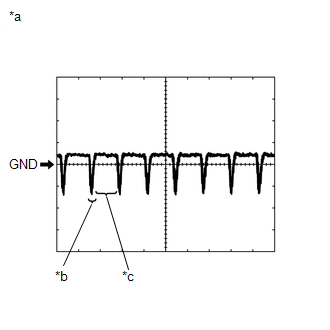
(2) Waveform 2 (camera lens covered, blacking out the screen)
|
Item |
Content |
|---|---|
|
Measurement terminal |
E51-12 (V+) - E38-7 (GND1) |
|
Measurement setting |
200 mV/DIV., 50 μs./DIV. |
|
Condition |
Ignition switch ON, shift lever in R |
HINT:
- The video waveform changes according to the image sent by the television camera assembly.
- The video waveform is constantly output when the ignition switch is turned to ACC.
|
*a |
Waveform 2 (camera lens covered, blacking out the screen) |
|
*b |
Synchronization Signal |
|
*c |
Video Waveform |
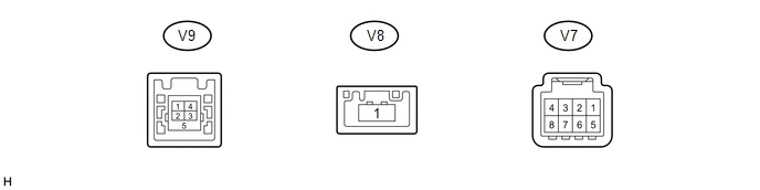
2. STEREO COMPONENT TUNER ASSEMBLY (w/ SDARS System)
|
Terminal No. (Symbol) |
Wiring Color |
Terminal Description |
Condition |
Specified Condition |
|---|---|---|---|---|
|
V7-3 (ACC2) - V7-8 (GND2) |
Y - B |
Power source (ACC) |
Ignition switch off |
Below 1 V |
|
Ignition switch ACC |
11 to 14 V |
|||
|
V7-4 (+B2) - V7-8 (GND2) |
R - B |
Power source (+B) |
Always |
11 to 14 V |
|
V7-8 (GND2) - Body ground |
B - Body ground |
Ground |
Always |
Below 1 V |
|
V9-1 (USV4) |
- |
Power source |
- |
- |
|
V9-2 (US4-) |
- |
Data signal |
- |
- |
|
V9-3 (US4+) |
- |
Data signal |
- |
- |
|
V9-4 (UGD4) |
- |
Ground |
- |
- |
|
V9-5 (USG4) |
- |
Shield ground |
- |
- |
|
V8-1 (LV1) |
- |
LVDS communication signal |
- |
- |
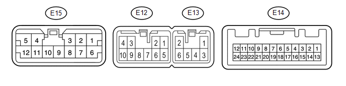
3. STEREO COMPONENT AMPLIFIER ASSEMBLY (for 13 Speakers)
|
Terminal No. (Symbol) |
Wiring Color |
Terminal Description |
Condition |
Specified Condition |
|---|---|---|---|---|
|
E13-1 (+B) - E13-2 (GND) |
R - W-B |
Power source (+B) |
Always |
11 to 14 V |
|
E13-2 (GND) - Body ground |
W-B - Body ground |
Ground |
Always |
Below 1 V |
|
E13-3 (+B2) - E13-2 (GND) |
R - W-B |
Power source (+B) |
Always |
11 to 14 V |
|
E13-6 (GND2) - Body ground |
W-B - Body ground |
Ground |
Always |
Below 1 V |
|
E14-1 (MUTE) - E13-2 (GND) |
LG - W-B |
Mute signal |
Audio system playing |
Above 3.5 V |
|
Audio system changing sources |
Below 1 V |
|||
|
E14-2 (L-) - E13-2 (GND) |
W - W-B |
Sound signal (Left) |
Audio system playing |
A waveform synchronized with sound signals is output |
|
E14-3 (L+) - E13-2 (GND) |
B - W-B |
Sound signal (Left) |
Audio system playing |
A waveform synchronized with sound signals is output |
|
E14-4 (R-) - E13-2 (GND) |
G - W-B |
Sound signal (Right) |
Audio system playing |
A waveform synchronized with sound signals is output |
|
E14-5 (R+) - E13-2 (GND) |
R - W-B |
Sound signal (Right) |
Audio system playing |
A waveform synchronized with sound signals is output |
|
E14-6 (SLD) - E13-2 (GND) |
Shield - W-B |
Shield ground |
Always |
Below 1 V |
|
E14-7 (TX-) |
G |
AVC-LAN communication signal |
- |
- |
|
E14-8 (TX+) |
R |
AVC-LAN communication signal |
- |
- |
|
E14-11 (SPD) - E13-2 (GND) |
P - W-B |
Vehicle speed signal |
Ignition switch ON Wheels being rotated |
Pulse generation |
|
E14-12 (ACC) - E13-2 (GND) |
G - W-B |
Power source (ACC) |
Ignition switch off |
Below 1 V |
|
Ignition switch ACC |
11 to 14 V |
|||
|
E14-14 (II1-) - E13-2(GND) |
B - W-B |
Voice signal |
Voice guidance sounding |
A waveform synchronized with voice signals is output |
|
E14-15 (II1+) - E13-2 (GND) |
W - W-B |
Voice signal |
Voice guidance sounding |
A waveform synchronized with voice signals is output |
|
E14-18 (SLD1) - E13-2 (GND) |
Shield - W-B |
Shield ground |
Always |
Below 1 V |
|
E12-1 (WFL+) - E13-2 (GND) |
LG - W-B |
Sound signal (Front left) |
Audio system playing |
A waveform synchronized with sound signals is output |
|
E12-2 (WFR+) - E13-2 (GND) |
P - W-B |
Sound signal (Front right) |
Audio system playing |
A waveform synchronized with sound signals is output |
|
E12-3 (CTR+) - E13-2 (GND) |
G - W-B |
Sound signal (Front center) |
Audio system playing |
A waveform synchronized with sound signals is output |
|
E12-4 (WF2+) - E13-2 (GND) |
P - W-B |
Sound signal (Rear right) |
Audio system playing |
A waveform synchronized with sound signals is output |
|
E12-5 (WFL-) - E13-2 (GND) |
L - W-B |
Sound signal (Front left) |
Audio system playing |
A waveform synchronized with sound signals is output |
|
E12-6 (WFR-) - E13-2 (GND) |
V - W-B |
Sound signal (Front right) |
Audio system playing |
A waveform synchronized with sound signals is output |
|
E12-7 (RR-) - E13-2 (GND) |
W - W-B |
Sound signal (Rear right) |
Audio system playing |
A waveform synchronized with sound signals is output |
|
E12-8 (RR+) - E13-2 (GND) |
R - W-B |
Sound signal (Rear right) |
Audio system playing |
A waveform synchronized with sound signals is output |
|
E12-9 (CTR-) - E13-2 (GND) |
R - W-B |
Sound signal (Front center) |
Audio system playing |
A waveform synchronized with sound signals is output |
|
E12-10 (WF2-) - E13-2 (GND) |
Y - W-B |
Sound signal (Rear right) |
Audio system playing |
A waveform synchronized with sound signals is output |
|
E15-1 (SL+) - E13-2 (GND) |
L - W-B |
Sound signal (Rear left) |
Audio system playing |
A waveform synchronized with sound signals is output |
|
E15-2 (SR+) - E13-2 (GND) |
LG - W-B |
Sound signal (Rear right) |
Audio system playing |
A waveform synchronized with sound signals is output |
|
E15-3 (FL+) - E13-2 (GND) |
G - W-B |
Sound signal (Front left) |
Audio system playing |
A waveform synchronized with sound signals is output |
|
E15-4 (RL+) - E13-2 (GND) |
B - W-B |
Sound signal (Rear left) |
Audio system playing |
A waveform synchronized with sound signals is output |
|
E15-5 (WF1+) - E13-2 (GND) |
P - W-B |
Sound signal (Rear left) |
Audio system playing |
A waveform synchronized with sound signals is output |
|
E15-6 (SL-) - E13-2 (GND) |
LG - W-B |
Sound -signal (Rear left) |
Audio system playing |
A waveform synchronized with sound signals is output |
|
E15-7 (SR-) - E13-2 (GND) |
L - W-B |
Sound signal (Rear right) |
Audio system playing |
A waveform synchronized with sound signals is output |
|
E15-8 (FL-) - E13-2 (GND) |
R - W-B |
Sound signal (Front left) |
Audio system playing |
A waveform synchronized with sound signals is output |
|
E15-9 (FR-) - E13-2 (GND) |
P - W-B |
Sound signal (Front right) |
Audio system playing |
A waveform synchronized with sound signals is output |
|
E15-10 (FR+) - E13-2 (GND) |
BR - W-B |
Sound signal (Front right) |
Audio system playing |
A waveform synchronized with sound signals is output |
|
E15-11 (RL-) - E13-2 (GND) |
Y - W-B |
Sound signal (Rear left) |
Audio system playing |
A waveform synchronized with sound signals is output |
|
E15-12 (WF1-) - E13-2 (GND) |
V - W-B |
Sound signal (Rear left) |
Audio system playing |
A waveform synchronized with sound signals is output |
 Problem Symptoms Table
PROBLEM SYMPTOMS TABLE
NOTICE:
After replacing the stereo component tuner assembly of vehicles subscribed to
pay-type satellite radio broadcasts, XM radio ID registration is necessary (w/ SDARS
...
 Dtc Check / Clear
DTC CHECK / CLEAR
1. CHECK DTC (CHECK USING TECHSTREAM)
(a) Connect the Techstream to the DLC3.
(b) Turn the ignition switch to ON.
(c) Turn the Techstream on.
(d) Enter the following menus: Body ...
Other materials about Toyota Venza:
Precaution
PRECAUTION
1. NOTICE FOR INITIALIZATION
HINT:
When disconnecting the cable from the negative (-) battery terminal, initialize
the following systems after the cable is reconnected.
System Name
See procedure
Back Door ...
System Diagram
SYSTEM DIAGRAM
1. CAN SIGNAL
2. DIRECT LINE SIGNAL
(a) Combination Meter Assembly
(b) Accessory Meter Assembly
3. INPUT AND OUTPUT SIGNALS OF THE COMBINATION METER ASSEMBLY OR ACCESSORY METER
ASSEMBLY
(a) Meter or Gauge
Meter or Gauge ...
A/C ECU Vehicle Information Reading/Writing Processor Malfunction (B15F5)
DESCRIPTION
This DTC is stored when items controlled by the air conditioning amplifier assembly
cannot be customized via the audio and visual system vehicle customization screen.
HINT:
The air conditioning amplifier assembly controls the air conditioning ...

0.1454