Toyota Venza: Installation
INSTALLATION
PROCEDURE
1. INSTALL RADIATOR ASSEMBLY
|
(a) Install the fan assembly with motor to the radiator with the 2 guides at the bottom and 3 snap fits on the top. Text in Illustration
|
|
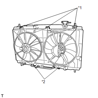
(b) Install the 2 lower radiator supports and 2 radiator support cushions.
|
(c) Install the radiator assembly and fan assembly with motor. NOTICE: Do not apply any excessive force to the cooler condenser assembly or pipe when installing the radiator assembly. |
|
|
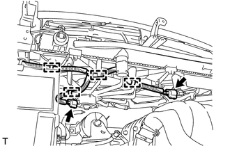
(d) Connect the 4 wire harness clamps and 2 connectors. |
|
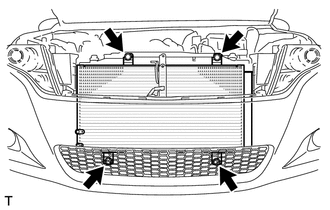
2. INSTALL COOLER CONDENSER ASSEMBLY
|
(a) Install the cooler condenser assembly with the 4 bolts. Torque: 5.0 N·m {51 kgf·cm, 44 in·lbf} |
|
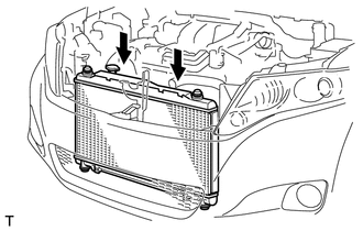
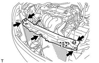
3. INSTALL UPPER RADIATOR SUPPORT
|
(a) Install the upper radiator support with the 5 bolts and connect the hood lock control cable clamp to the upper radiator support. Torque: 12 N·m {122 kgf·cm, 9 ft·lbf} |
|
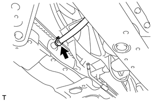
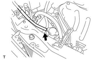
4. CONNECT OUTLET NO. 1 OIL COOLER HOSE
|
(a) Connect the outlet No. 1 oil cooler hose to the radiator. |
|
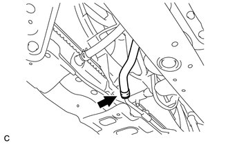
5. CONNECT INLET NO. 1 OIL COOLER HOSE
|
(a) Connect the inlet No. 1 oil cooler hose to the radiator. |
|
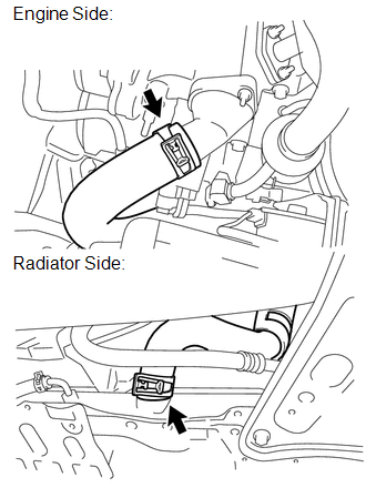
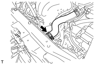
6. INSTALL NO. 2 RADIATOR HOSE
|
(a) Install the No. 2 radiator hose to the engine and radiator. |
|
7. CONNECT NO. 1 RADIATOR HOSE
|
(a) Connect the No. 1 radiator hose to the radiator. |
|
8. CONNECT OUTLET RESERVE TANK HOSE
|
(a) Connect the outlet reserve tank hose to the radiator. |
|
9. INSTALL HOOD LOCK ASSEMBLY (w/o Engine Hood Courtesy Switch)
.gif)
10. INSTALL HOOD LOCK ASSEMBLY (w/ Engine Hood Courtesy Switch)
11. INSTALL LOW PITCHED HORN ASSEMBLY
12. INSTALL HIGH PITCHED HORN ASSEMBLY
13. INSTALL RADIATOR GRILLE
14. INSTALL INLET AIR CLEANER ASSEMBLY
15. ADD ENGINE COOLANT
16. INSPECT FOR COOLANT LEAK
17. INSPECT AUTOMATIC TRANSAXLE FLUID
HINT:
- U760F Automatic transaxle: See page
- U760E Automatic transaxle: See page
18. INSTALL NO. 1 ENGINE UNDER COVER
19. INSTALL NO. 2 ENGINE UNDER COVER
20. INSTALL COOL AIR INTAKE DUCT SEAL
 On-vehicle Inspection
ON-VEHICLE INSPECTION
PROCEDURE
1. CHECK RADIATOR CAP SUB-ASSEMBLY
(a) Measure the valve opening pressure.
(1) If there are water stains or foreign matter on rubber packings 1, 2 or 3,
clean t ...
 Removal
REMOVAL
PROCEDURE
1. REMOVE NO. 1 ENGINE UNDER COVER
2. REMOVE NO. 2 ENGINE UNDER COVER
3. DRAIN ENGINE COOLANT
4. REMOVE COOL AIR INTAKE DUCT SEAL
5. REMOVE INLET AIR CLEANER ASSEMBLY
...
Other materials about Toyota Venza:
Poor Sound Quality in All Modes (Low Volume)
PROCEDURE
1.
CHECK AUDIO SETTINGS
(a) Set treble, middle and bass to the initial values and check that the sound
is normal.
OK:
The sound returns to normal.
HINT:
Sound quality adjustment measures vary according to the ...
Evaporative Emission Control System Pressure Sensor Range / Performance (P0451-P0453)
DTC SUMMARY
DTC No.
Monitoring Item
Malfunction Detection Condition
Trouble Area
Detection Timing
Detection Logic
P0451
Canister pressure sensor abnormal voltage flu ...
Installation
INSTALLATION
PROCEDURE
1. TEMPORARILY TIGHTEN COMPRESSOR AND MAGNETIC CLUTCH
(a) Temporarily install the compressor and magnetic clutch and bracket
with the 4 bolts.
2. INSTALL COMPRESSOR AND MA ...

0.1212