
Toyota Venza: Test Mode Procedure
TEST MODE PROCEDURE
1. ENTER TEST MODE (SIGNAL CHECK MODE)
(a) Turn the ignition switch off.
(b) Connect the Techstream to the DLC3.
(c) Turn the ignition switch to ON.
(d) Check that the tire pressure warning light comes on for 3 seconds and then goes off.
(e) Turn the Techstream on.
(f) Enter the following menus: Chassis / Tire Pressure Monitor / Utility / Signal Check.
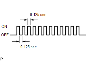
(g) Confirm that the tire pressure warning light in the accessory meter blinks at 0.125 second intervals.
2. PERFORM SIGNAL CHECK
HINT:
- When entering signal check mode, the tire pressure warning ECU sets all the signal check DTCs (test mode DTCs) first.
- After the tire pressure warning ECU completes the signal check for each inspection item, the DTCs for systems that are determined to be normal will be cleared.
- The DTCs for other inspection items may not be cleared when only a certain signal is inspected.
- When signal check returns to normal mode, all the signal check DTCs will be cleared.
(a) Turn the ignition switch off.
(b) Connect the Techstream to the DLC3.
(c) Turn the ignition switch to ON.
(d) Turn the Techstream on.
(e) Enter the following menus: Chassis / Tire Pressure Monitor / Utility / Signal Check.
HINT:
Every time the conditions to clear signal check DTCs are met, the tire pressure warning light comes on for 1 second. Following this, the tire pressure warning light blinks at 0.125 second intervals.
(f) Start the engine and allow it to run at 1000 rpm for 3 seconds or more to check the engine speed signal (C2194/94).
(g) Drive the vehicle at 20 km/h (12 mph) or more for 3 seconds or more to check the vehicle speed signal (C2191/91).
(h) Loosen each valve core and rapidly reduce the pressure (at least 40 kPa (0.4 kg/cm2, 5.8 psi) within 30 seconds) to check the transmitter data (C2181/81 to C2184/84).
HINT:
The transmitter ID will be transmitted if the tire pressure is reduced rapidly.
(i) Check that the tire pressure warning system signal check DTCs are cleared.
|
Signal Check DTC |
Test Signal |
Signal Check DTC Clear Condition |
|---|---|---|
|
C2181/81 to C2184/84 |
Transmitter Data |
Data is received from the transmitter which has a registered ID in the tire pressure warning ECU |
|
C2191/91 |
Vehicle Speed Signal |
Vehicle speed of 20 km/h (12 mph) or more is detected for 3 seconds or more |
|
C2194/94 |
Engine Speed Signal |
Engine speed of 1000 rpm or more is detected for 3 seconds or more |
(j) Result
HINT:
After the signal check is completed, check for signal check DTCs to confirm the system status.
|
Condition |
Procedure |
|---|---|
|
Signal check DTC is output |
Repair the faulty part and enter SIGNAL CHECK again |
|
Signal check DTCs are cleared |
No problem |
(k) Make a note of any signal check DTCs that are output.
(l) End of signal check mode
(1) After completing signal check mode, turn the ignition switch off and disconnect the Techstream.
(m) Signal check (test mode) DTCs
(1) If a trouble code was displayed during the signal check mode DTC check, check the circuit listed for that code. For details of each code, refer to See Procedure below.
|
DTC No. |
Detection Item |
Trouble Area |
See Procedure |
|---|---|---|---|
|
C2181/81 |
Transmitter ID1 not received |
|
|
|
C2182/82 |
Transmitter ID2 not received |
|
|
|
C2183/83 |
Transmitter ID3 not received |
|
|
|
C2184/84 |
Transmitter ID4 not received |
|
|
|
C2191/91 |
Vehicle speed signal error |
|
|
|
C2194/94 |
Engine speed signal error |
|
|
.gif)
 Problem Symptoms Table
PROBLEM SYMPTOMS TABLE
HINT:
Use the table below to help determine the cause of problem symptoms.
If multiple suspected areas are listed, the potential causes of the symptoms
are lis ...
 Diagnosis System
DIAGNOSIS SYSTEM
1. CHECK BATTERY VOLTAGE
Standard voltage:
11 to 14 V
If the voltage is below 11 V, recharge the battery before proceeding to the next
step.
2. CHECK DLC3
(a) The ECU uses IS ...
Other materials about Toyota Venza:
Tcm
Components
COMPONENTS
ILLUSTRATION
Removal
REMOVAL
CAUTION / NOTICE / HINT
NOTICE:
If automatic transmission parts are replaced, refer to Parts Replacement Compensation
Table to determine if any additional operations are necessary (See page
). ...
Removal
REMOVAL
PROCEDURE
1. DISCONNECT CABLE FROM NEGATIVE BATTERY TERMINAL
CAUTION:
Wait at least 90 seconds after disconnecting the cable from the negative (-)
battery terminal to disable the SRS system (See page
).
NOTICE:
When disconnecting the cable, s ...
Installation
INSTALLATION
PROCEDURE
1. INSTALL REAR NO. 3 SPEAKER ASSEMBLY
(a) Install the rear No. 3 speaker assembly with the 2 bolts.
(b) Engage the clamp.
2. INSTALL ROOF SIDE INNER GARNISH ASSEMBLY LH
...

0.1775