Toyota Venza: Inspection
INSPECTION
PROCEDURE
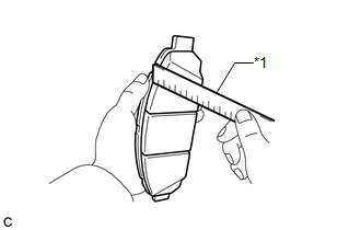
1. INSPECT PAD LINING THICKNESS
|
(a) Using a ruler, measure the pad lining thickness. Text in Illustration
Standard thickness of a new pad: 12.0 mm (0.472 in.) Minimum thickness: 1.0 mm (0.0394 in.) If the pad lining thickness is equal to or less than the minimum, replace the disc brake pads. HINT: Be sure to check the wear of the front disc after replacing the brake pads with new ones. |
|
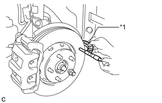
2. INSPECT DISC THICKNESS
|
(a) Using a micrometer, measure the disc thickness. Text in Illustration
Standard thickness of a new disc: 28.0 mm (1.10 in.) Minimum thickness: 26.0 mm (1.02 in.) HINT: If the disc thickness is less than the minimum, replace the front disc. |
|
3. INSPECT DISC RUNOUT
(a) Inspect the front axle hub bearing looseness and front axle hub runout (See
page .gif) ).
).
|
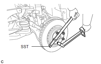
(b) Using SST to hold the disc, tighten the disc with the 5 hub nuts. SST: 09330-00021 Torque: 103 N·m {1050 kgf·cm, 76 ft·lbf} |
|
|
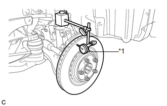
(c) Using a dial indicator, measure the disc runout 10 mm (0.394 in.) away from the outer edge of the front disc. Text in Illustration
Maximum disc runout: 0.05 mm (0.00197 in.) If the runout exceeds the maximum, change the installation position of the disc to minimize runout. If the runout exceeds the maximum even when the installation position is changed, grind the disc. If the disc thickness is less than the minimum, replace the front disc. NOTICE: Keep the magnetic parts of the dial indicator away from the front axle hub and speed sensor. |
|
(d) Remove the 5 hub nuts and front disc.
 Removal
REMOVAL
CAUTION / NOTICE / HINT
HINT:
Use the same procedure for the LH side and RH side.
The following procedure listed is for the LH side.
PROCEDURE
1. REMOVE FRONT WHEEL
2. ...
 Installation
INSTALLATION
PROCEDURE
1. TEMPORARILY TIGHTEN FRONT DISC BRAKE BLEEDER PLUG
(a) Temporarily tighten the front disc brake bleeder plug.
HINT:
Fully tighten the front disc brake bleeder plug after ...
Other materials about Toyota Venza:
Reassembly
REASSEMBLY
PROCEDURE
1. INSTALL FRONT SEAT WIRE RH (for Front Passenger Side)
(a) Engage each clamp and install the front seat wire RH.
2. INSTALL OCCUPANT CLASSIFICATION ECU (for Front Passenger Side)
3. INSTALL SEAT POSITION SENSOR
4. INSTALL SEA ...
Front passenger occupant classification system
Your vehicle is equipped with a front passenger occupant classification system.
This system detects the conditions of the front passenger seat and activates or
deactivates the devices for front passenger.
1. SRS warning light
2. Front passenger’s sea ...
Dtc Check / Clear
DTC CHECK / CLEAR
1. CHECK DTC
(a) Connect the Techstream to the DLC3.
(b) Turn the ignition switch to ON and turn the Techstream on.
(c) Enter the following menus: Body Electrical / Trouble Codes.
(d) Check for DTCs.
2. CLEAR DTC
(a) Connect the Techst ...

0.164