Toyota Venza: Atf Temperature Sensor(when Using The Engine Support Bridge)
Components
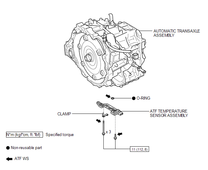
COMPONENTS
ILLUSTRATION
Inspection
INSPECTION
PROCEDURE
1. INSPECT ATF TEMPERATURE SENSOR ASSEMBLY
|
(a) Measure the resistance according to the value(s) in the table below. Standard Resistance:
If the resistance is out of the specified range with the ATF temperature shown in the preceding table, replace the ATF temperature sensor assembly. Otherwise, the driveability of the vehicle may decrease. |
|
.png)
Removal
REMOVAL
PROCEDURE
1. REMOVE VALVE BODY OIL STRAINER ASSEMBLY
See page .gif)
2. REMOVE ATF TEMPERATURE SENSOR ASSEMBLY
|
(a) Disconnect the ATF temperature sensor assembly connector. Text in Illustration
|
|
.png)
(b) Remove the 4 bolts, ATF temperature sensor assembly and clamp from the transmission valve body assembly.
|
(c) Remove the O-ring from the ATF temperature sensor assembly. Text in Illustration
|
|
.png)
Installation
INSTALLATION
PROCEDURE
1. INSTALL ATF TEMPERATURE SENSOR ASSEMBLY
(a) Coat a new O-ring with ATF and install it to the ATF temperature sensor assembly.
(b) Coat the 4 bolts with ATF.
|
(c) Install the ATF temperature sensor assembly and clamp to the transmission valve body assembly with the 4 bolts. Text in Illustration
Torque: 11 N·m {112 kgf·cm, 8 ft·lbf} Bolt Length: Bolt (A) 25 mm (0.984 in.) Bolt (B) 85 mm (3.35 in.) |
|
.png)
(d) Connect the ATF temperature sensor assembly connector.
2. INSTALL VALVE BODY OIL STRAINER ASSEMBLY
See page .gif)
 Installation
INSTALLATION
PROCEDURE
1. INSTALL ATF TEMPERATURE SENSOR ASSEMBLY
(a) Coat a new O-ring with ATF and install it to the ATF temperature
sensor assembly.
Text in Illustration
...

Other materials about Toyota Venza:
Disassembly
DISASSEMBLY
PROCEDURE
1. REMOVE FRONT DRIVE SHAFT HOLE SNAP RING (for LH Side)
(a) Using a screwdriver, remove the front drive shaft hole snap ring.
2. REMOVE NO. 2 FRONT AXLE INBOARD JOINT BOOT CLA ...
Air Mix Damper Control Servo Motor Circuit (Driver Side) (B1446/46)
DESCRIPTION
The air mix control servo motor sends pulse signals to indicate the damper position
to the A/C amplifier. The A/C amplifier activates the motor (normal or reverse)
based on these signals to move the air mix damper (driver side) to any position ...
Adjustment
ADJUSTMENT
CAUTION / NOTICE / HINT
CAUTION:
Before adjusting the door positions of vehicles equipped with side and curtain
shield airbags, be sure to disconnect the battery. After adjustment, check that
the SRS warning light is operating normally and ...

0.1718