Toyota Venza: Installation
INSTALLATION
PROCEDURE
1. INSTALL SEPARATE TYPE FRONT SEATBACK COVER
|
(a) Using a tacker, install the separate type front seatback heater to the end of the separate type front seatback cover with 12 new tack pins. NOTICE: Be careful not to damage the cushion. |
|
.png)
|
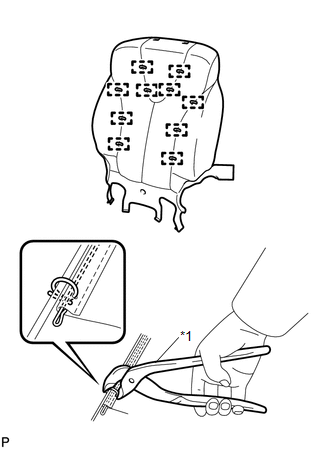
(b) Using hog ring pliers, install the separate type front seatback cover with 10 new hog rings. Text in Illustration
NOTICE:
|
|
2. INSTALL SEPARATE TYPE FRONT SEATBACK COVER WITH PAD
.gif)
3. INSTALL FRONT SEATBACK BOARD SUB-ASSEMBLY
4. INSTALL SEPARATE TYPE FRONT SEAT CUSHION COVER WITH PAD
5. INSTALL FRONT INNER SEAT CUSHION SHIELD
6. INSTALL FRONT SEAT INNER BELT ASSEMBLY
7. INSTALL POWER SEAT SWITCH
8. INSTALL FRONT SEAT CUSHION SHIELD ASSEMBLY
9. INSTALL SLIDE AND VERTICAL POWER SEAT SWITCH KNOB
10. INSTALL RECLINING POWER SEAT SWITCH KNOB
11. INSTALL FRONT SEAT ASSEMBLY
12. INSTALL FRONT SEAT REAR INNER TRACK COVER
13. INSTALL FRONT SEAT REAR OUTER TRACK COVER
14. INSTALL FRONT SEAT HEADREST ASSEMBLY
15. INSPECT FRONT SEAT ASSEMBLY
16. INSPECT SRS WARNING LIGHT
(See page )
 Inspection
INSPECTION
PROCEDURE
1. INSPECT FRONT SEATBACK HEATER LH
(a) Apply battery voltage and check the seatback heater.
OK:
Measurement Connection
Cond ...

Other materials about Toyota Venza:
Transmitter ID1 Operation Stop (C2111/11-C2114/14)
DESCRIPTION
The tire pressure warning valve and transmitter installed in each tire and wheel
assembly measures the tire pressures. The measured values are transmitted as radio
waves to the tire pressure warning antenna and receiver on the body and then se ...
Hill-start assist control
Hill-start assist control helps to prevent the vehicle from rolling backwards
when starting on incline or slippery slope.
To engage hill-start assist control, further depress the brake pedal when the
vehicle is stopped completely.
A buzzer will sound o ...
Removal
REMOVAL
PROCEDURE
1. REMOVE FRONT SEAT ASSEMBLY LH
(See page )
2. REMOVE FRONT DOOR SCUFF PLATE LH
3. REMOVE COWL SIDE TRIM SUB-ASSEMBLY LH
4. REMOVE FRONT DOOR OPENING TRIM WEATHERSTRIP LH
5. REMOVE REAR DOOR SCUFF PLATE LH
6. REMOVE REAR ...

0.1595