Toyota Venza: Removal
REMOVAL
PROCEDURE
1. REMOVE NO. 1 ENGINE UNDER COVER
2. REMOVE NO. 2 ENGINE UNDER COVER
3. REMOVE WINDSHIELD WIPER MOTOR AND LINK
(a) Remove the windshield wiper motor and link (See page
.gif) ).
).
4. REMOVE OUTER COWL TOP PANEL SUB-ASSEMBLY
5. DRAIN ENGINE COOLANT
6. REMOVE NO. 1 ENGINE COVER SUB-ASSEMBLY
7. REMOVE NO. 1 VACUUM SWITCHING VALVE ASSEMBLY
8. REMOVE AIR CLEANER CAP SUB-ASSEMBLY
9. REMOVE AIR CLEANER FILTER ELEMENT SUB-ASSEMBLY
10. REMOVE AIR CLEANER CASE
11. REMOVE ENGINE COOLANT TEMPERATURE SENSOR
|
(a) Disconnect the engine coolant temperature sensor connector. Text in Illustration
|
|
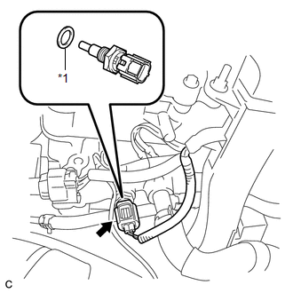
(b) Remove the engine coolant temperature sensor and gasket.
 Inspection
INSPECTION
PROCEDURE
1. INSPECT ENGINE COOLANT TEMPERATURE SENSOR
Text in Illustration
*1
Component without harness connected
(Engine Coolant Temperature Sensor)
...
 Installation
INSTALLATION
PROCEDURE
1. INSTALL ENGINE COOLANT TEMPERATURE SENSOR
(a) Install a new gasket to the sensor.
Text in Illustration
*1
New Gasket
...
Other materials about Toyota Venza:
Removal
REMOVAL
PROCEDURE
1. DISCONNECT CABLE FROM NEGATIVE BATTERY TERMINAL
NOTICE:
When disconnecting the cable, some systems need to be initialized after the cable
is reconnected (See page ).
2. REMOVE FRONT WHEEL RH
3. REMOVE NO. 1 ENGINE UNDER COVER
4. ...
On-vehicle Inspection
ON-VEHICLE INSPECTION
PROCEDURE
1. INSPECT REAR WIPER MOTOR AND BRACKET ASSEMBLY
(a) Operate the rear wiper motor and bracket assembly.
(b) Stop the rear wiper motor and bracket assembly operation.
...
Evaporative Emission System Leak Detection Reference Orifice Low Flow (P043E,P043F,P2401,P2402,P2419)
DTC SUMMARY
DTC No.
Monitoring Item
Malfunction Detection Condition
Trouble Area
Detection Timing
Detection Logic
P043E
Reference orifice clogged
P043E, P ...

0.1389