Toyota Venza: Installation
INSTALLATION
PROCEDURE
1. INSTALL POWER OUTLET SOCKET COVER NO.1
|
(a) Engage the 2 claws to install the power point socket cover. |
|
.png)
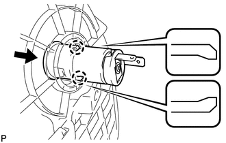
2. INSTALL POWER POINT SOCKET ASSEMBLY
|
(a) Engage the 2 claws to install the power point socket assembly as shown in the illustration. |
|
3. INSTALL CONSOLE BOX SUB-ASSEMBLY
.gif)
4. INSTALL POSITION INDICATOR HOUSING ASSEMBLY
5. INSTALL SHIFT LEVER KNOB SUB-ASSEMBLY
6. INSTALL LOWER INSTRUMENT PANEL SUB-ASSEMBLY
7. INSTALL NO. 2 INSTRUMENT PANEL UNDER COVER SUB-ASSEMBLY
8. INSTALL COWL SIDE TRIM SUB-ASSEMBLY RH
9. INSTALL FRONT DOOR SCUFF PLATE RH
10. INSTALL LOWER NO. 1 INSTRUMENT PANEL FINISH PANEL
11. INSTALL COWL SIDE TRIM SUB-ASSEMBLY LH
12. INSTALL FRONT DOOR SCUFF PLATE LH
13. INSTALL AIR CONDITIONING CONTROL ASSEMBLY
14. INSTALL CONSOLE BOX ASSEMBLY
15. INSTALL NO. 2 CONSOLE BOX CARPET
16. INSTALL UPPER CONSOLE PANEL SUB-ASSEMBLY (w/o Seat Heater System)
17. INSTALL UPPER CONSOLE PANEL SUB-ASSEMBLY (w/ Seat Heater System)
 Removal
REMOVAL
PROCEDURE
1. REMOVE UPPER CONSOLE PANEL SUB-ASSEMBLY (w/o Seat Heater System)
2. REMOVE UPPER CONSOLE PANEL SUB-ASSEMBLY (w/ Seat Heater System)
3. REMOVE NO. 2 CONSOLE BOX CARPET
...

Other materials about Toyota Venza:
Installation
INSTALLATION
PROCEDURE
1. INSTALL FRONT NO. 1 STABILIZER BAR BUSHING
(a) Install the 2 front No. 1 stabilizer bar bushings to the front stabilizer
bar as shown in the illustration.
Text in Illustration
*1
...
VSC OFF Indicator Light Remains ON
DESCRIPTION
The skid control ECU is connected to the combination meter via CAN communication.
Pressing the VSC OFF switch turns off traction control and pressing and holding
this switch turns off traction and VSC controls. If VSC control is turned off, the ...
Evaporative Emission Control System Pressure Sensor Range / Performance (P0451-P0453)
DTC SUMMARY
DTC No.
Monitoring Item
Malfunction Detection Condition
Trouble Area
Detection Timing
Detection Logic
P0451
Canister pressure sensor abnormal voltage flu ...

0.138