Toyota Venza: Inspection
INSPECTION
PROCEDURE
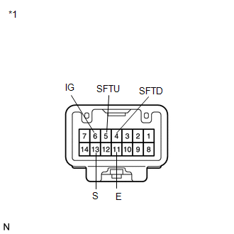
1. INSPECT SHIFT LOCK CONTROL UNIT ASSEMBLY (w/o Smart Key System)
|
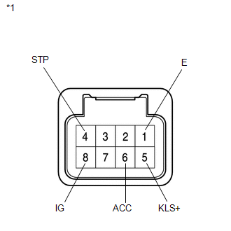
(a) Measure the voltage according to the value(s) in the table below. Text in Illustration
Standard Voltage:
HINT: Do not disconnect the shift lock control unit assembly connector. |
|
|
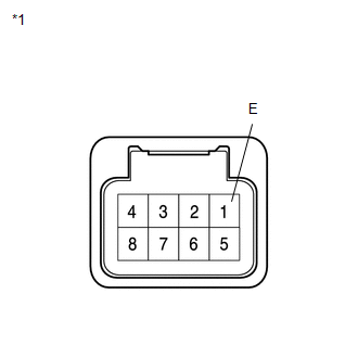
(b) Measure the resistance according to the value(s) in the table below. Text in Illustration
Standard Resistance:
HINT: Do not disconnect the shift lock control unit assembly connector. If the result is not as specified, replace the shift lever assembly. |
|
2. INSPECT SHIFT LOCK CONTROL UNIT ASSEMBLY (w/ Smart Key System)
|
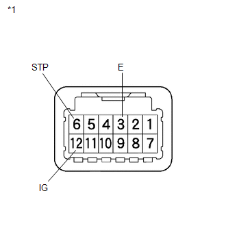
(a) Measure the voltage according to the value(s) in the table below. Text in Illustration
Standard Voltage:
HINT: Do not disconnect the shift lock control unit assembly connector. If the result is not as specified, replace the shift lock control unit assembly. |
|
|
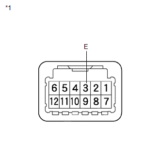
(b) Measure the resistance according to the value(s) in the table below. Text in Illustration
Standard Resistance:
HINT: Do not disconnect the shift lock control unit assembly connector. If the result is not as specified, replace the shift lock control unit assembly. |
|
3. INSPECT TRANSMISSION CONTROL SWITCH
|
(a) Measure the resistance between each terminal of the shift lock control unit assembly when the shift lever is moved to each position. Text in Illustration
Standard Resistance:
If the result is not as specified, replace the shift lock control unit assembly. |
|
4. INSPECT SHIFT LOCK SOLENOID
(a) Disconnect the shift lock solenoid connector.
|
(b) Measure the resistance according to the value(s) in the table below when the shift lever is moved to each position. Text in Illustration
Standard Resistance:
If the result is not as specified, replace the shift lock control unit assembly. |
|
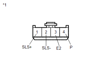
(c) Measure the resistance according to the value(s) in the table below.
Standard Resistance:
|
Tester Connection |
Condition |
Specified Condition |
|---|---|---|
|
1 (SLS+) - 2 (SLS-) |
Always |
112 Ω |
If the result is not as specified, replace the shift lock control unit assembly.
 Removal
REMOVAL
PROCEDURE
1. DISCONNECT CABLE FROM NEGATIVE BATTERY TERMINAL
NOTICE:
When disconnecting the cable, some systems need to be initialized after the cable
is reconnected (See page ).
2. RE ...
 Installation
INSTALLATION
PROCEDURE
1. INSTALL SHIFT LEVER ASSEMBLY
NOTICE:
Check that the park/neutral position switch and the shift lever are in neutral.
(a) Slide the slider of the transmission ...
Other materials about Toyota Venza:
Disassembly
DISASSEMBLY
PROCEDURE
1. REMOVE ULTRASONIC SENSOR CLIP (w/ Intuitive Parking Assist System)
2. REMOVE NO. 1 ULTRASONIC SENSOR (w/ Intuitive Parking Assist System)
3. REMOVE NO. 1 ULTRASONIC SENSOR RETAINER (w/ Intuitive Parking Assist System)
4. ...
No Sound can be Heard from Speakers
PROCEDURE
1.
CHECK AUDIO SETTINGS
(a) In sound setting mode, set volume, fader and balance to the initial values
and check that the sound is normal.
OK:
Audio system returns to normal.
HINT:
Sound quality adjustment mea ...
Problem Symptoms Table
PROBLEM SYMPTOMS TABLE
Use the table below to help determine the cause of problem symptoms. If multiple
suspected areas are listed, the potential causes of the symptoms are listed in order
of probability in the "Suspected Area" column of the tab ...

0.1716