Toyota Venza: Washer Nozzle(for Front Side)
Components
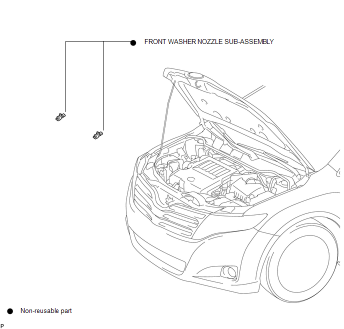
COMPONENTS
ILLUSTRATION
On-vehicle Inspection
ON-VEHICLE INSPECTION
PROCEDURE
1. INSPECT FRONT WASHER NOZZLE SUB-ASSEMBLY
(a) With the engine running, check that the center stream of washer fluid sprays on the windshield within the area shown in the illustration.
OK:
Washer fluid hits the windshield in the area shown in the illustration.
If the result is not as specified, replace the washer nozzle.
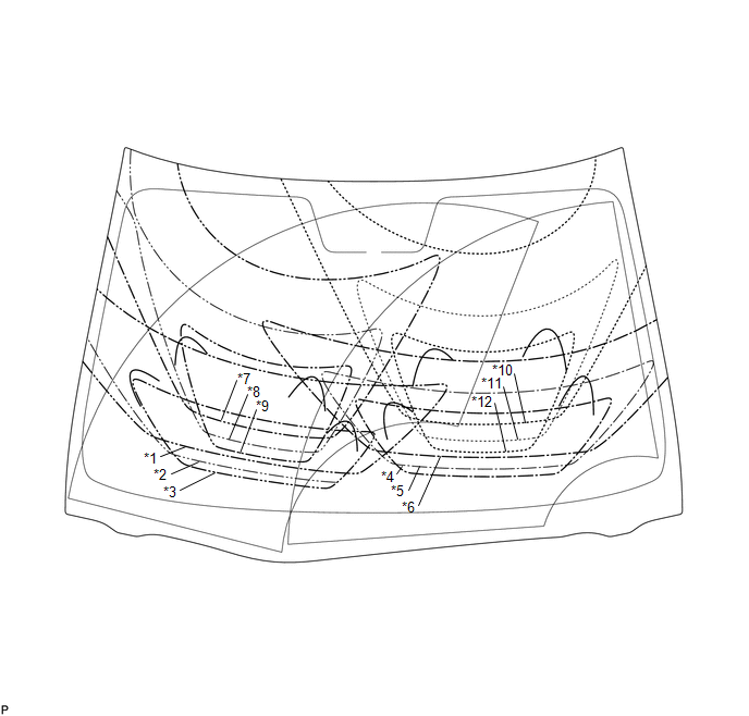 Text in Illustration
|
*1 |
Front Passenger Side Lower Maximum Spray |
*7 |
Front Passenger Side Upper Maximum Spray |
|
*2 |
Front Passenger Side Lower Nominal Spray |
*8 |
Front Passenger Side Upper Nominal Spray |
|
*3 |
Front Passenger Side Lower Minimum Spray |
*9 |
Front Passenger Side Upper Minimum Spray |
|
*4 |
Driver Side Lower Maximum Spray |
*10 |
Driver Side Upper Maximum Spray |
|
*5 |
Driver Side Lower Nominal Spray |
*11 |
Driver Side Upper Nominal Spray |
|
*6 |
Driver Side Lower Minimum Spray |
*12 |
Driver Side Upper Minimum Spray |
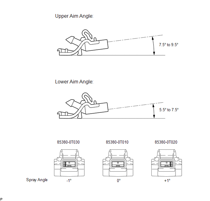
Adjustment
ADJUSTMENT
PROCEDURE
1. ADJUST FRONT WASHER NOZZLE SUB-ASSEMBLY
(a) Select a washer nozzle so that the washer fluid spray area is within the standard range. Replace the washer nozzle with the selected one.
Removal
REMOVAL
PROCEDURE
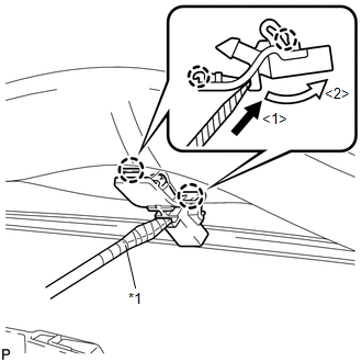
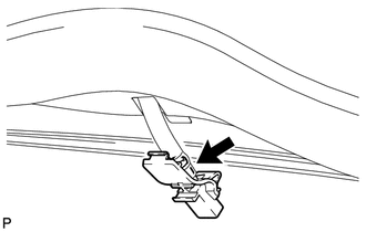
1. REMOVE FRONT WASHER NOZZLE SUB-ASSEMBLY
|
(a) Using a screwdriver, disengage the 2 claws and separate the washer nozzle sub-assembly as shown in the illustration. NOTICE: Be careful not to damage the windshield. HINT: Tape the screwdriver tip before use. Text in Illustration
|
|
|
(b) Remove the washer nozzle sub-assembly from the washer hose. NOTICE: Washer nozzles cannot be reused. |
|
Installation
INSTALLATION
PROCEDURE
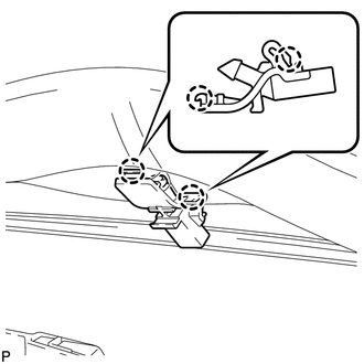
1. INSTALL FRONT WASHER NOZZLE SUB-ASSEMBLY
|
(a) Connect a new front washer nozzle sub-assembly to the washer hose. |
|
.png)
|
(b) Engage the 2 claws and install the front washer nozzle sub-assembly. |
|
2. INSPECT FRONT WASHER NOZZLE SUB-ASSEMBLY
.gif)
3. ADJUST FRONT WASHER NOZZLE SUB-ASSEMBLY
 Washer Motor(for Rear Side)
Components
COMPONENTS
ILLUSTRATION
Removal
REMOVAL
PROCEDURE
1. REMOVE FRONT WHEEL RH
2. REMOVE FRONT FENDER OUTSIDE MOULDING RH
HINT:
Use the same procedure for the RH side and LH side ...
 Washer Nozzle(for Rear Side)
Components
COMPONENTS
ILLUSTRATION
On-vehicle Inspection
ON-VEHICLE INSPECTION
PROCEDURE
1. INSPECT REAR WASHER NOZZLE
(a) With the engine running, check where the washer fluid hits the w ...
Other materials about Toyota Venza:
Emission Control System
Parts Location
PARTS LOCATION
ILLUSTRATION
On-vehicle Inspection
ON-VEHICLE INSPECTION
PROCEDURE
1. INSPECT FUEL CUT-OFF RPM
(a) Increase the engine speed to at least 3500 rpm.
(b) Use a sound scope to check for injector operating soun ...
ECM / PCM Processor (P0606)
MONITOR DESCRIPTION
The ECM continuously monitors its main and sub CPUs. This self-check ensures
that the ECM is functioning properly. If outputs from the CPUs are different and
deviate from the standard, the ECM illuminates the MIL and stores the DTC imm ...
Removal
REMOVAL
CAUTION / NOTICE / HINT
NOTICE:
When disconnecting the steering intermediate shaft assembly and pinion shaft
of steering gear assembly, be sure to place matchmarks before servicing.
PROCEDURE
1. PLACE FRONT WHEELS FACING STRAIGHT AHEAD
2. SECUR ...

0.1286