Toyota Venza: Removal
REMOVAL
PROCEDURE
1. REMOVE UPPER CONSOLE PANEL SUB-ASSEMBLY (w/o Seat Heater System)
.gif)
2. REMOVE UPPER CONSOLE PANEL SUB-ASSEMBLY (w/ Seat Heater System)
3. REMOVE NO. 2 CONSOLE BOX CARPET
4. REMOVE CONSOLE BOX ASSEMBLY
5. REMOVE AIR CONDITIONING CONTROL ASSEMBLY
6. REMOVE FRONT DOOR SCUFF PLATE LH
7. REMOVE COWL SIDE TRIM SUB-ASSEMBLY LH
8. REMOVE LOWER NO. 1 INSTRUMENT PANEL FINISH PANEL
9. REMOVE FRONT DOOR SCUFF PLATE RH
10. REMOVE COWL SIDE TRIM SUB-ASSEMBLY RH
11. REMOVE NO. 2 INSTRUMENT PANEL UNDER COVER SUB-ASSEMBLY
12. REMOVE LOWER INSTRUMENT PANEL SUB-ASSEMBLY
13. REMOVE SHIFT LEVER KNOB SUB-ASSEMBLY
14. REMOVE POSITION INDICATOR HOUSING ASSEMBLY
15. REMOVE CONSOLE BOX SUB-ASSEMBLY
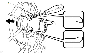
16. REMOVE POWER POINT SOCKET ASSEMBLY
|
(a) Using a screwdriver, disengage the 2 claws and remove the power point socket assembly as shown in the illustration. Text in Illustration
HINT: Tape the screwdriver tip before use. |
|
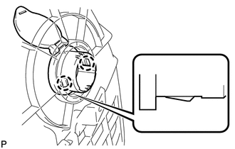
17. REMOVE POWER OUTLET SOCKET COVER NO.1
|
(a) Disengage the 2 claws and remove the power point socket cover. |
|
 Components
COMPONENTS
ILLUSTRATION
ILLUSTRATION
...
 Installation
INSTALLATION
PROCEDURE
1. INSTALL POWER OUTLET SOCKET COVER NO.1
(a) Engage the 2 claws to install the power point socket cover.
2. INSTAL ...
Other materials about Toyota Venza:
Terminals Of Ecu
TERMINALS OF ECU
1. STEERING LOCK ECU (STEERING LOCK ACTUATOR ASSEMBLY)
Terminal No. (Symbol)
Wiring Color
Terminal Description
Condition
Specified Condition
D17-1 (GND) - Body ground
...
ABS Control System Malfunction (43)
DESCRIPTION
This DTC is output when the VSC system detects a malfunction in the ABS control
system.
DTC Code
DTC Detection Condition
Trouble Area
43
Malfunction in the ABS control system.
...
Data List / Active Test
DATA LIST / ACTIVE TEST
1. DATA LIST
HINT:
Using the Techstream to read the Data List allows the values or states of switches,
sensors, actuator and other items to be read without removing any parts. This non-intrusive
inspection can be very useful beca ...

0.1257