
Toyota Venza: Inspection
INSPECTION
PROCEDURE
1. INSPECT THERMOSTAT
HINT:
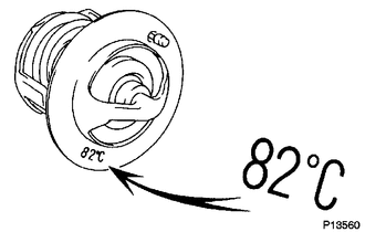
The valve opening temperature is inscribed on the thermostat.
|
(a) Immerse the thermostat in water, and then gradually heat the water. |
|
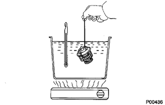
(b) Check that the valve of the thermostat opens at the specified temperature.
Standard valve opening temperature:
80 to 84°C (176 to 183°F)
If the valve does not open as specified, replace the thermostat.
|
(c) Check the valve lift. Standard valve lift: 10 mm (0.394 in.) or more at 95°C (203°F) If the valve lift is not as specified, replace the thermostat. |
|
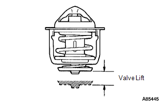
(d) Check that the valve is fully closed when the thermostat is at a low temperature (below 77°C (171°F)).
If the valve is not fully closed, replace the thermostat.
 Removal
REMOVAL
PROCEDURE
1. DISCONNECT CABLE FROM NEGATIVE BATTERY TERMINAL
NOTICE:
When disconnecting the cable, some systems need to be initialized after the cable
is reconnected (See page ).
2. RE ...
 Installation
INSTALLATION
PROCEDURE
1. INSTALL THERMOSTAT
(a) Install a new gasket to the thermostat.
(b) Install the thermostat with the jiggle valve facing upward.
HINT:
The jiggle valve may ...
Other materials about Toyota Venza:
Antenna Coil Open / Short (B2784)
DESCRIPTION
This DTC is stored when there is an open or short in the transponder key coil
(built into the engine switch).
DTC No.
DTC Detection Condition
Trouble Area
B2784
Transponder key coil i ...
Noise Occurs or Sound Skips when Portable Player Plays
CAUTION / NOTICE / HINT
HINT:
Perform this check with the portable player volume set at an appropriate
level.
Make sure that there are no obstructions between the portable player
and navigation receiver assembly that may block signals, an ...
Trip information
Display items can be switched by pressing the “INFO” button.
- Average Fuel Economy
Displays the average fuel consumption since the function was reset.
• The function can be reset by pressing and holding the “SELECT RESET” button
when the ...

0.1185