Toyota Venza: Air Mix Damper Control Servo Motor Circuit (Passenger Side) (B1441/41)
DESCRIPTION
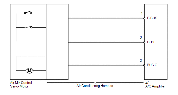
The air mix control servo motor sends pulse signals to indicate the damper position to the A/C amplifier. The A/C amplifier activates the motor (normal or reverse) based on these signals to move the air mix damper (front passenger side) to any position. As a result, the amount of air passing through the heater core after passing through the evaporator is adjusted, and the temperature of the air blowing toward the passenger side is controlled.
The A/C amplifier communicates with the servo through a communication/driver IC and wiring assembly called the air conditioning harness.
HINT:
Confirm that no mechanical problem is present because this DTC can be output when either a damper link or the damper is mechanically locked.
|
DTC No. |
DTC Detection Condition |
Trouble Area |
|---|---|---|
|
B1441/41 |
Air mix damper position sensor value does not change even if A/C amplifier operates air mix control servo motor |
|
WIRING DIAGRAM
PROCEDURE
|
1. |
READ VALUE USING TECHSTREAM |
(a) Connect the Techstream to the DLC3.
(b) Turn the ignition switch to ON.
(c) Turn the Techstream on.
(d) Operate the front passenger side temperature adjustment switch.
(e) Enter the following menus: Body / Air Conditioner / Data List.
(f) Check the value(s) by referring to the table below.
Air Conditioner|
Tester Display |
Measurement Item/Range |
Normal Condition |
Diagnostic Note |
|---|---|---|---|
|
Air Mix Servo Targ Pulse (P) |
Passenger side air mix servo motor target pulse / Min.: 0, Max.: 255 |
MAX. COLD: 105 (pulse) MAX. HOT: 7 (pulse) |
- |
OK:
The display is as specified in the Normal Condition column.
|
Result |
Proceed to |
|---|---|
|
NG |
A |
|
OK (When troubleshooting according to Problem Symptoms Table) |
B |
|
OK (When troubleshooting according to the DTC) |
C |
| B | .gif) |
PROCEED TO NEXT SUSPECTED AREA SHOWN IN PROBLEM SYMPTOMS TABLE |
| C | |
REPLACE A/C AMPLIFIER |
|
.gif)
|
2. |
PERFORM ACTIVE TEST USING TECHSTREAM |
(a) Connect the Techstream to the DLC3.
(b) Turn the ignition switch to ON.
(c) Turn the Techstream on.
(d) Enter the following menus: Body / Air Conditioner / Active Test.
(e) Check the operation by referring to the table below.
Air Conditioner|
Tester Display |
Test Part |
Control Range |
Diagnostic Note |
|---|---|---|---|
|
Air Mix Servo Targ Pulse (P) |
Air mix servo motor pulse (P side) |
Min.: 0, Max.: 255 |
- |
OK:
Air temperature changes in accordance with each control range.
| OK | |
REPLACE A/C AMPLIFIER |
|
|
3. |
INSPECT AIR MIX CONTROL SERVO MOTOR |
(a) Replace the air mix control servo motor (See page
.gif) ).
).
HINT:
Since the servo motor cannot be inspected while it is removed from the vehicle, replace the servo motor with a new or a known good one and check that the condition returns to normal.
(b) Check for the DTC.
|
Result |
Proceed to |
|---|---|
|
DTC B1441/41 is output |
A |
|
DTC B1441/41 is not output |
B |
| B | |
REPLACE AIR MIX CONTROL SERVO MOTOR |
|
|
4. |
INSPECT AIR CONDITIONING HARNESS |
(a) Replace the air conditioning harness (See page
).
HINT:
Since the air conditioning harness cannot be inspected while it is removed from the vehicle, replace the air conditioning harness with a new or a known good one and check that the condition returns to normal.
(b) Check for the DTC.
|
Result |
Proceed to |
|---|---|
|
DTC B1441/41 is output |
A |
|
DTC B1441/41 is not output |
B |
| A | |
REPLACE A/C AMPLIFIER |
| B | |
REPLACE AIR CONDITIONING HARNESS |
 Air Outlet Damper Control Servo Motor Circuit (B1443/43)
DESCRIPTION
The air outlet control servo motor sends pulse signals to indicate the damper
position to the A/C amplifier. The A/C amplifier activates the motor (normal or
reverse) based on these s ...
 Pressure Sensor Circuit (B1423/23)
DESCRIPTION
This DTC is output when refrigerant pressure on the high pressure side is extremely
low (190 kPa (1.9 kgf/cm2, 28 psi) or less) or extremely high (3140 kPa (32.0 kgf/cm2,
455 psi) or ...
Other materials about Toyota Venza:
Inspection
INSPECTION
PROCEDURE
1. INSPECT ENGINE SWITCH
(a) Measure the resistance according to the value(s) in the table below.
Standard Resistance:
Tester Connection
Switch Condition
Specified Condition
7 (SS1) ...
Skid Control ECU Communication Stop Mode
DESCRIPTION
Detection Item
Symptom
Trouble Area
Skid Control ECU Communication Stop Mode
"ABS/VSC/TRAC" is not displayed on "CAN Bus Check" screen of
the Techstr ...
Door Mirror Foot Light Circuit
DESCRIPTION
The main body ECU (driver side junction block assembly) controls the door mirror
foot lights.
WIRING DIAGRAM
1. w/o Seat Position Memory:
2. w/ Seat Position Memory:
PROCEDURE
1.
CHECK VEHICLE CONDITION
...

0.143