Toyota Venza: System Diagram
SYSTEM DIAGRAM
1. CAN AND DIRECT LINE SIGNALS
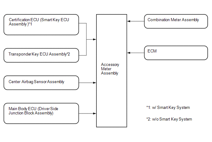
2. INPUT AND OUTPUT SIGNALS OF THE ACCESSORY METER ASSEMBLY
|
Warning light or indicator light |
Communication Signal |
Receiver |
Communication Line |
Sender |
|---|---|---|---|---|
|
Front passenger side seat belt warning light |
Front passenger side seat belt warning light |
Accessory Meter Assembly |
Direct Line |
Combination Meter Assembly |
|
Tire pressure warning light |
Tire pressure warning light |
Accessory Meter Assembly |
Direct Line |
Combination Meter Assembly |
|
AWD warning light*1 |
AWD warning light |
Accessory Meter Assembly |
Direct Line |
Combination Meter Assembly |
|
Slip indicator light |
Slip indicator light |
Accessory Meter Assembly |
Direct Line |
Combination Meter Assembly |
|
VSC OFF indicator light |
VSC OFF indicator light |
Accessory Meter Assembly |
Direct Line |
Combination Meter Assembly |
|
EPS warning light |
EPS warning light |
Accessory Meter Assembly |
Direct Line |
Combination Meter Assembly |
|
Washer level warning light |
Washer level warning light |
Accessory Meter Assembly |
Direct Line |
Combination Meter Assembly |
|
TRAC OFF indicator light |
TRAC OFF indicator light |
Accessory Meter Assembly |
Direct Line |
Combination Meter Assembly |
|
Security indicator light |
Security indicator light |
Accessory Meter Assembly |
Direct Line |
Transponder Key ECU Assembly*2 |
|
Certification ECU (Smart Key ECU Assembly)*3 |
||||
|
Key indicator light*3 |
Key indicator light |
Accessory Meter Assembly |
Direct Line |
Certification ECU (Smart Key ECU Assembly) |
|
Passenger airbag ON/OFF indicator light |
Passenger airbag ON/OFF indicator light |
Accessory Meter Assembly |
Direct Line |
Center Airbag Sensor Assembly |
|
MIL (Check engine warning light) |
MIL (Check engine warning light) |
Accessory Meter Assembly |
Direct Line |
ECM |
|
Cruise information display |
Cruise information display |
Accessory Meter Assembly |
Direct Line |
Combination Meter Assembly |
|
Air conditioning display |
Air conditioning display |
Accessory Meter Assembly |
Direct Line |
Combination Meter Assembly |
|
Each system warning display*4 |
Each system warning |
Accessory Meter Assembly |
Direct Line |
Combination Meter Assembly |
|
Each system customize display |
Each system customize |
Accessory Meter Assembly |
Direct Line |
Combination Meter Assembly |
|
DTC (Diagnostic Trouble Code) display |
DTC display |
Accessory Meter Assembly |
Direct Line |
Combination Meter Assembly |
- *1: for AWD
- *2: w/o Smart Key System
- *3: w/ Smart Key System
- *4: w/ Multi-information Display
 Parts Location
PARTS LOCATION
ILLUSTRATION
ILLUSTRATION
...
 How To Proceed With Troubleshooting
CAUTION / NOTICE / HINT
HINT:
Use the following procedure to troubleshoot.
PROCEDURE
1.
VEHICLE BROUGHT TO WORKSHOP
NEXT
...
Other materials about Toyota Venza:
Installation
INSTALLATION
PROCEDURE
1. INSTALL ENGINE MOUNTING DAMPER
(a) Install the engine mounting damper with the 3 bolts.
Torque:
9.0 N·m {92 kgf·cm, 80 in·lbf}
2. INSTALL WIRING HARNESS CLAMP BRA ...
Reassembly
REASSEMBLY
CAUTION / NOTICE / HINT
NOTICE:
Before installation, apply high temperature grease to the parts indicated by
arrows (See page ).
PROCEDURE
1. INSTALL NO. 2 PARKING BRAKE SHOE HOLD DOWN SPRING PIN (for 2WD)
(a) Install the No. 2 p ...
Back Door Closer Switch Malfunction (B2251)
DESCRIPTION
The power back door ECU (power back door motor unit)*1 or back door closer ECU
(multiplex network door ECU)*2 receives signals from the latch switch, sector switch
and back door courtesy switch, which are built into the back door lock. Based o ...

0.1551