Toyota Venza: Installation
INSTALLATION
PROCEDURE
1. INSTALL THERMOSTAT
(a) Install a new gasket to the thermostat.
|
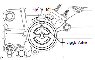
(b) Install the thermostat with the jiggle valve facing upward. HINT: The jiggle valve may be set to within 10° on either side of the prescribed position. |
|
2. INSTALL WATER INLET
|
(a) Install the water inlet with the 2 nuts. Torque: 10 N·m {102 kgf·cm, 7 ft·lbf} |
|
.png)
3. CONNECT NO. 2 RADIATOR HOSE
.gif)
4. INSTALL GENERATOR ASSEMBLY
5. INSTALL WIRE HARNESS CLAMP BRACKET
6. INSTALL V-RIBBED BELT
HINT:
See page
7. CONNECT CABLE TO NEGATIVE BATTERY TERMINAL
NOTICE:
When disconnecting the cable, some systems need to be initialized after the cable
is reconnected (See page ).
8. ADD ENGINE COOLANT
9. INSPECT FOR COOLANT LEAK
10. INSTALL COOL AIR INTAKE DUCT SEAL
11. INSTALL NO. 1 ENGINE UNDER COVER
12. INSTALL NO. 2 ENGINE UNDER COVER
13. INSTALL NO. 1 ENGINE COVER SUB-ASSEMBLY
 Inspection
INSPECTION
PROCEDURE
1. INSPECT THERMOSTAT
HINT:
The valve opening temperature is inscribed on the thermostat.
(a) Immerse the thermostat in water, and then gradually heat the water. ...
 Water Pump
...
Other materials about Toyota Venza:
Windshield Deicer does not Operate
DESCRIPTION
When the rear window defogger switch on the air conditioning control assembly
is pressed, the operation signal is transmitted to the air conditioning amplifier
assembly through the LIN communication line. When the air conditioning amplifier
...
Removal
REMOVAL
PROCEDURE
1. REMOVE REAR SEAT HEADREST ASSEMBLY
2. REMOVE REAR SEAT CENTER HEADREST ASSEMBLY
3. REMOVE REAR SEAT INNER TRACK BRACKET COVER
4. REMOVE REAR SEAT OUTER TRACK BRACKET COVER
5. DISCONNECT REAR SEAT RECLINING CONTROL CABLE S ...
Removal
REMOVAL
PROCEDURE
1. DISCONNECT CABLE FROM NEGATIVE BATTERY TERMINAL
CAUTION:
Wait at least 90 seconds after disconnecting the cable from the negative (-)
battery terminal to disable the SRS system (See page
).
NOTICE:
When disconnecting the cable, s ...

0.1158