Toyota Venza: Inspection
INSPECTION
PROCEDURE
1. INSPECT SHIFT SOLENOID VALVE SL
|
(a) Measure the resistance according to the value(s) in the table below. Text in Illustration
Standard Resistance:
If the value is not as specified, replace the shift solenoid valve. |
|
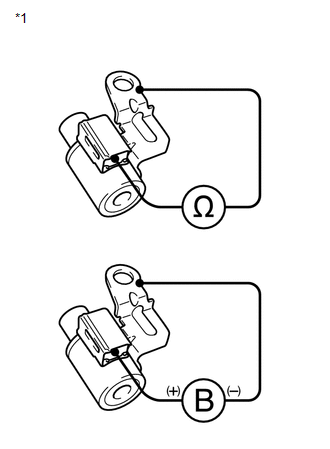
(b) Connect a positive (+) battery lead to the terminal of the solenoid connector, and a negative (-) battery lead to the solenoid body, and check the operation of the valve.
NOTICE:
When using battery voltage during the inspection, do not bring the positive (+) and negative (-) tester probes too close to each other as a short circuit may occur.
OK:
The valve moves and makes an operating sound.
If the operation cannot be done as specified, replace the shift solenoid valve.
2. INSPECT SHIFT SOLENOID VALVE SLT
|
(a) Measure the resistance according to the value(s) in the table below. Text in Illustration
Standard Resistance:
If the value is not as specified, replace the shift solenoid valve. |
|
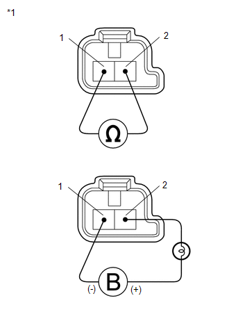
(b) Connect a positive (+) battery lead with a 21 W bulb to terminal 2 and a negative (-) battery lead to terminal 1 of the solenoid valve connector, and check the operation of the valve.
NOTICE:
When using battery voltage during the inspection, do not bring the positive (+) and negative (-) tester probes too close to each other as a short circuit may occur.
OK:
The valve moves and makes an operating sound.
If the operation cannot be done as specified, replace the shift solenoid valve.
3. INSPECT SHIFT SOLENOID VALVE SLU
|
(a) Measure the resistance according to the value(s) in the table below. Text in Illustration
Standard Resistance:
If the value is not as specified, replace the shift solenoid valve. |
|
(b) Connect a positive (+) battery lead with a 21 W bulb to terminal 2 and a negative (-) battery lead to terminal 1 of the solenoid valve connector, and check the operation of the valve.
NOTICE:
When using battery voltage during the inspection, do not bring the positive (+) and negative (-) tester probes too close to each other as a short circuit may occur.
OK:
The valve moves and makes an operating sound.
If the operation cannot be done as specified, replace the shift solenoid valve.
4. INSPECT SHIFT SOLENOID VALVE SL1
|
(a) Measure the resistance according to the value(s) in the table below. Text in Illustration
Standard Resistance:
If the value is not as specified, replace the shift solenoid valve. |
|
(b) Connect a positive (+) battery lead with a 21 W bulb to terminal 2 and a negative (-) battery lead to terminal 1 of the solenoid valve connector, and check the operation of the valve.
NOTICE:
When using battery voltage during the inspection, do not bring the positive (+) and negative (-) tester probes too close to each other as a short circuit may occur.
OK:
The valve moves and makes an operating sound.
If the operation cannot be done as specified, replace the shift solenoid valve.
5. INSPECT SHIFT SOLENOID VALVE SL2
|
(a) Measure the resistance according to the value(s) in the table below. Text in Illustration
Standard Resistance:
If the value is not as specified, replace the shift solenoid valve. |
|
(b) Connect a positive (+) battery lead with a 21 W bulb to terminal 2 and a negative (-) battery lead to terminal 1 of the solenoid valve connector, and check the operation of the valve.
NOTICE:
When using battery voltage during the inspection, do not bring the positive (+) and negative (-) tester probes too close to each other as a short circuit may occur.
OK:
The valve moves and makes an operating sound.
If the operation cannot be done as specified, replace the shift solenoid valve.
6. INSPECT SHIFT SOLENOID VALVE SL3
|
(a) Measure the resistance according to the value(s) in the table below. Text in Illustration
Standard Resistance:
If the value is not as specified, replace the shift solenoid valve. |
|
(b) Connect a positive (+) battery lead with a 21 W bulb to terminal 2 and a negative (-) battery lead to terminal 1 of the solenoid valve connector, and check the operation of the valve.
NOTICE:
When using battery voltage during the inspection, do not bring the positive (+) and negative (-) tester probes too close to each other as a short circuit may occur.
OK:
The valve moves and makes an operating sound.
If the operation cannot be done as specified, replace the shift solenoid valve.
7. INSPECT SHIFT SOLENOID VALVE SL4
|
(a) Measure the resistance according to the value(s) in the table below. Text in Illustration
Standard Resistance:
If the value is not as specified, replace the shift solenoid valve. |
|
(b) Connect a positive (+) battery lead with a 21 W bulb to terminal 2 and a negative (-) battery lead to terminal 1 of the solenoid valve connector, and check the operation of the valve.
NOTICE:
When using battery voltage during the inspection, do not bring the positive (+) and negative (-) tester probes too close to each other as a short circuit may occur.
OK:
The valve moves and makes an operating sound.
If the operation cannot be done as specified, replace the shift solenoid valve.
 Removal
REMOVAL
PROCEDURE
1. REMOVE AUTOMATIC TRANSAXLE ASSEMBLY
HINT:
See the steps from "Remove Engine Assembly with transaxle" through "Remove Automatic
Transaxle Assembly" (See p ...
 Reassembly
REASSEMBLY
PROCEDURE
1. INSTALL SHIFT SOLENOID VALVE SL4
(a) Coat the shift solenoid valve SL4 and bolt with ATF.
Text in Illustration
*1
Lock Pla ...
Other materials about Toyota Venza:
Installation
INSTALLATION
PROCEDURE
1. INSTALL BRAKE MASTER CYLINDER SUB-ASSEMBLY
NOTICE:
When install a new brake master cylinder sub-assembly, remove the protectors
from the piston and outlet ports.
(a) Install a new O-ring to the brake master cylinder sub-assembl ...
Check Mode Procedure
CHECK MODE PROCEDURE
1. DESCRIPTION
(a) Check mode has a higher sensitivity to malfunctions and can detect malfunctions
that normal mode cannot detect. Check mode can also detect all the malfunctions
that normal mode can detect. In check mode, DTCs are d ...
Motor Circuit Malfunction (C1521,C1531-C1534,C1554)
DESCRIPTION
If the power steering ECU detects these DTCs, it will shut off the motor relay
circuit (built into the power steering ECU) and stop power assist. However, power
assist continues if DTC C1533 or C1534 is stored.
DTC No.
D ...

0.1382