Toyota Venza: Reassembly
REASSEMBLY
PROCEDURE
1. INSTALL SHIFT SOLENOID VALVE SL4
|
(a) Coat the shift solenoid valve SL4 and bolt with ATF. Text in Illustration
|
|
.png)
(b) Install the shift solenoid valve SL4 and lock plate to the valve body assembly with the bolt.
Torque:
11 N·m {112 kgf·cm, 8 ft·lbf}
2. INSTALL SHIFT SOLENOID VALVE SL3
|
(a) Coat the shift solenoid valve SL3 and bolt with ATF. Text in Illustration
|
|
.png)
(b) Install the shift solenoid valve SL3 and lock plate to the valve body assembly with the bolt.
Torque:
11 N·m {112 kgf·cm, 8 ft·lbf}
3. INSTALL SHIFT SOLENOID VALVE SL1
|
(a) Coat the shift solenoid valve SL1 with ATF. Text in Illustration
|
|
.png)
(b) Install the shift solenoid valve SL1 to the valve body assembly.
4. INSTALL SHIFT SOLENOID VALVE SL2
(a) Coat the shift solenoid valve SL2 and bolt with ATF.
(b) Install the shift solenoid valve SL2 and lock plate to the valve body assembly with the bolt.
Torque:
11 N·m {112 kgf·cm, 8 ft·lbf}
5. INSTALL SHIFT SOLENOID VALVE SLU
|
(a) Coat the shift solenoid valve SLU with ATF. Text in Illustration
|
|
.png)
(b) Install the shift solenoid valve SLU to the valve body assembly.
6. INSTALL SHIFT SOLENOID VALVE SLT
(a) Coat the shift solenoid valve SLT with ATF.
(b) Install the shift solenoid valve SLT and lock plate to the valve body assembly.
7. INSTALL SHIFT SOLENOID VALVE SL
|
(a) Coat the shift solenoid valve SL with ATF. |
|
.png)
(b) Install the shift solenoid valve SL to the valve body assembly.
8. INSTALL ATF TEMPERATURE SENSOR ASSEMBLY
|
(a) Coat a new O-ring with ATF and install it to the ATF temperature sensor assembly. Text in Illustration
|
|
.png)
|
(b) Coat the 4 bolts with ATF. Text in Illustration
|
|
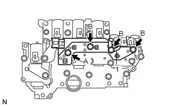
(c) Install the ATF temperature sensor assembly and clamp to the valve body assembly with the 4 bolts.
Torque:
11 N·m {112 kgf·cm, 8 ft·lbf}
Bolt length:
Bolt A
25 mm (0.984 in.)
Bolt B
85 mm (3.35 in.)
9. INSTALL TRANSMISSION WIRE
.gif)
 Inspection
INSPECTION
PROCEDURE
1. INSPECT SHIFT SOLENOID VALVE SL
(a) Measure the resistance according to the value(s) in the table below.
Text in Illustration
*1
...
 Installation
INSTALLATION
PROCEDURE
1. INSTALL MANUAL VALVE
(a) Coat the manual valve with ATF and install it to the transmission
valve body assembly.
...
Other materials about Toyota Venza:
Removal
REMOVAL
PROCEDURE
1. REMOVE INNER REAR VIEW MIRROR STAY HOLDER COVER
(a) Disengage the 2 claws and slide the inner rear view mirror stay holder
cover as shown in the illustration.
(b) ...
Yaw Rate Sensor Output Malfunction (C1448/98)
DESCRIPTION
The skid control ECU receives signals from the yaw rate and acceleration sensor
via the CAN communication system.
The yaw rate sensor has a built-in acceleration sensor and detects the vehicle
condition.
DTC Code
DTC De ...
Disposal
DISPOSAL
CAUTION / NOTICE / HINT
CAUTION:
Before performing pre-disposal deployment of any SRS component, review and closely
follow all applicable environmental and hazardous material regulations. Pre-disposal
deployment may be considered hazardous mate ...

0.1607