Toyota Venza: Door Mirror Foot Light
Components
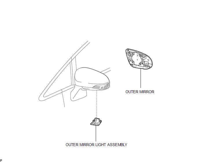
COMPONENTS
ILLUSTRATION
Removal
REMOVAL
CAUTION / NOTICE / HINT
HINT:
- Use the same procedure for both the RH and LH sides.
- The procedure described below is for the LH side.
PROCEDURE
1. REMOVE OUTER MIRROR
.gif)
2. REMOVE OUTER MIRROR LIGHT ASSEMBLY
|
(a) Disengage the 2 claws and guide from the outer rear view mirror assembly. |
|
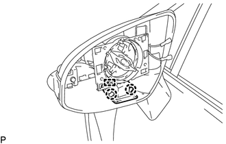
(b) Disconnect the connector and remove the outer mirror light assembly.
Inspection
INSPECTION
PROCEDURE
1. INSPECT OUTER MIRROR LIGHT ASSEMBLY LH
|
(a) Connect a positive (+) lead from the battery to terminal 1 and a negative (-) lead to terminal 2. |
|
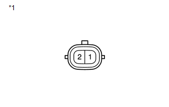
(b) Check that the outer mirror foot light comes on.
OK:
The light comes on.
Text in Illustration|
*1 |
Component without harness connected (Outer Mirror Light Assembly LH) |
If the result is not as specified, replace the outer mirror light assembly LH.
2. INSPECT OUTER MIRROR LIGHT ASSEMBLY RH
|
(a) Connect a positive (+) lead from the battery to terminal 1 and a negative (-) lead to terminal 2. |
|
(b) Check that the outer mirror foot light comes on.
OK:
The light comes on.
Text in Illustration|
*1 |
Component without harness connected (Outer Mirror Light Assembly RH) |
If the result is not as specified, replace the outer mirror light assembly RH.
Installation
INSTALLATION
CAUTION / NOTICE / HINT
HINT:
- Use the same procedure for both the RH and LH sides.
- The procedure described below is for the LH side.
PROCEDURE
1. INSTALL OUTER MIRROR LIGHT ASSEMBLY
(a) Connect the connector.
(b) Engage the guide and 2 claws to install the outer mirror light assembly.
2. INSTALL OUTER MIRROR
.gif)
 Automatic Light Control Sensor
Components
COMPONENTS
ILLUSTRATION
Removal
REMOVAL
PROCEDURE
1. REMOVE DEFROSTER NOZZLE GARNISH
2. REMOVE AUTOMATIC LIGHT CONTROL SENSOR
(a) Disengage the 2 claws and remov ...
 Fog Light Assembly
Components
COMPONENTS
ILLUSTRATION
Disassembly
DISASSEMBLY
PROCEDURE
1. REMOVE FOG LIGHT BULB
(a) Turn the fog light bulb in the direction indicated by the arrow shown
in t ...
Other materials about Toyota Venza:
Removal
REMOVAL
CAUTION / NOTICE / HINT
NOTICE:
If automatic transaxle assembly parts are replaced, refer to Parts Replacement
Compensation Table to determine if any additional operations are necessary (See
page ).
PROCEDURE
1. DISCHARGE FUEL PRESSURE
See p ...
Installation
INSTALLATION
PROCEDURE
1. INSTALL STEERING PAD
(a) Check that the ignition switch is off.
(b) Check that the cable is disconnected from the negative (-) battery terminal.
CAUTION:
Wait at least 90 seconds after disconnecting the cable from the negative ( ...
Terminals Of Ecu
TERMINALS OF ECU
1. CHECK COMBINATION METER ASSEMBLY
(a) Measure the resistance and voltage according to the value(s) in the table
below.
Tester Connection
Wiring Color
Terminal Description
Condition
...

0.1711