Toyota Venza: Removal
REMOVAL
PROCEDURE
1. REMOVE AUTOMATIC TRANSAXLE ASSEMBLY
HINT:
See the steps from "Remove Engine Assembly with transaxle" through "Remove Automatic
Transaxle Assembly" (See page .gif) ).
).
2. REMOVE AUTOMATIC TRANSAXLE OIL PAN SUB-ASSEMBLY
|
(a) Remove the 18 bolts and automatic transaxle oil pan sub-assembly from the automatic transaxle assembly. NOTICE: Some fluid will remain in the automatic transaxle oil pan sub-assembly. Remove all the bolts, and carefully remove the automatic transaxle oil pan sub-assembly. |
|
.png)
(b) Remove the automatic transaxle oil pan gasket from the automatic transaxle oil pan sub-assembly.
|
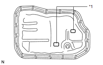
(c) Remove the 2 transmission oil cleaner magnets from the automatic transaxle oil pan sub-assembly. Text in Illustration
|
|
|
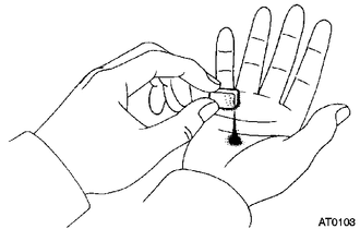
(d) Examine particles in the automatic transaxle oil pan sub-assembly. (1) Use the removed transmission oil cleaner magnets to collect any steel chips. Examine the chips and particles in the automatic transaxle oil pan sub-assembly and on the transmission oil cleaner magnets to determine what type of wear has occurred in the automatic transaxle assembly: Result: Steel (magnetic) Bearing, gear and plate wear Brass (non-magnetic) Bushing wear |
|
3. REMOVE VALVE BODY OIL STRAINER ASSEMBLY
|
(a) Remove the 2 bolts and valve body oil strainer assembly from the transmission valve body assembly. |
|
.png)
|
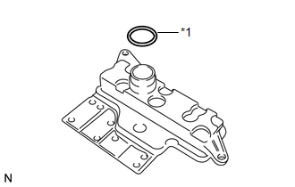
(b) Remove the O-ring from the valve body oil strainer assembly. Text in Illustration
|
|
4. REMOVE TRANSMISSION VALVE BODY ASSEMBLY
|
(a) Remove the 11 bolts and transmission valve body assembly from the automatic transaxle assembly. NOTICE: When removing the transmission valve body assembly, be careful not to allow the speed sensor and the automatic transaxle assembly to interfere with each other. |
|
.png)
5. REMOVE MANUAL VALVE
|
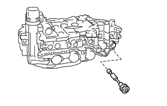
(a) Remove the manual valve from the transmission valve body assembly. |
|
 Disassembly
DISASSEMBLY
PROCEDURE
1. REMOVE TRANSMISSION WIRE
2. REMOVE ATF TEMPERATURE SENSOR ASSEMBLY
(a) Remove the 4 bolts, ATF temperature sensor assembly and clamp from
the valve body ...
 Inspection
INSPECTION
PROCEDURE
1. INSPECT SHIFT SOLENOID VALVE SL
(a) Measure the resistance according to the value(s) in the table below.
Text in Illustration
*1
...
Other materials about Toyota Venza:
Seat Heater System
Precaution
PRECAUTION
1. NOTICE FOR INITIALIZATION
HINT:
When disconnecting the cable from the negative (-) battery terminal, initialize
the following systems after the cable is reconnected.
System Name
See procedure
...
Removal
REMOVAL
CAUTION / NOTICE / HINT
NOTICE:
Do not remove the oil pump or oil pump relief valve from the timing chain cover
sub-assembly.
PROCEDURE
1. INSTALL ENGINE ON ENGINE STAND
(See page )
2. REMOVE IGNITION COIL ASSEMBLY
3. REMOVE CYLINDER HEAD ...
Removal
REMOVAL
CAUTION / NOTICE / HINT
HINT:
Use the same procedure for the RH side and LH side.
The procedure listed below is for the LH side.
PROCEDURE
1. REMOVE REAR WHEEL
2. SEPARATE REAR SPEED SENSOR
(a) Remove the bolt and se ...

0.1842