Toyota Venza: Inspection
INSPECTION
PROCEDURE
1. INSPECT FRONT NO. 2 SPEAKER ASSEMBLY (for 6 Speakers)
(a) With the speaker installed, check that there is no looseness or other abnormalities.
(b) Check that there is no foreign matter in the speaker, no tears on the speaker cone or other abnormalities.
|
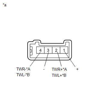
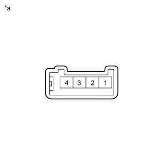
(c) Measure the resistance of the speaker. Standard Resistance:
If the result is not as specified, replace the speaker. Text in Illustration
|
|
(d) When there is a possibility that either the right or left speaker is malfunctioning, interchange the speakers and perform an inspection. If the malfunction disappears after interchanging the speakers, replace the malfunctioning speaker.
HINT:
Connect all connectors to the speakers when performing an inspection. If the result is not as specified, replace the speaker.
2. INSPECT FRONT NO. 2 SPEAKER ASSEMBLY (for 13 Speakers)
(a) With the speaker installed, check that there is no looseness or other abnormalities.
(b) Check that there is no foreign matter in the speaker, no tears on the speaker cone or other abnormalities.
|
(c) Measure the resistance of the speaker. Standard Resistance:
If the result is not as specified, replace the speaker. Text in Illustration
|
|
3. INSPECT FRONT NO. 3 SPEAKER ASSEMBLY (for 13 Speakers)
(a) With the speaker installed, check that there is no looseness or other abnormalities.
(b) Check that there is no foreign matter in the speaker, no tears on the speaker cone or other abnormalities.
|
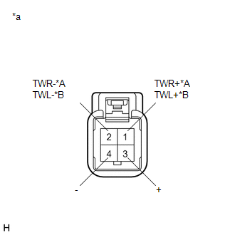
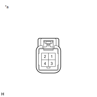
(c) Measure the resistance of the speaker. Standard Resistance:
If the result is not as specified, replace the speaker. Text in Illustration
|
|
(d) When there is a possibility that either the right or left speaker is malfunctioning, interchange the speakers and perform an inspection. If the malfunction disappears after interchanging the speakers, replace the malfunctioning speaker.
HINT:
Connect all connectors to the speakers when performing an inspection. If the result is not as specified, replace the speaker.
4. INSPECT FRONT NO. 4 SPEAKER ASSEMBLY (for 13 Speakers)
(a) With the speaker installed, check that there is no looseness or other abnormalities.
(b) Check that there is no foreign matter in the speaker, no tears on the speaker cone or other abnormalities.
|
(c) Measure the resistance of the speaker. Standard Resistance:
If the result is not as specified, replace the speaker. Text in Illustration
|
|
 Removal
REMOVAL
PROCEDURE
1. DISCONNECT FRONT DOOR OPENING TRIM WEATHERSTRIP
2. REMOVE FRONT PILLAR GARNISH
3. REMOVE NO. 2 INSTRUMENT PANEL SPEAKER PANEL SUB-ASSEMBLY
4. REMOVE FRONT NO. 4 SPEA ...
 Installation
INSTALLATION
PROCEDURE
1. INSTALL FRONT NO. 3 SPEAKER ASSEMBLY (for 13 Speakers)
(a) Engage the 3 claws to install the front No. 3 speaker assembly.
...
Other materials about Toyota Venza:
Mass or Volume Air Flow Circuit Low Input (P0102,P0103)
DESCRIPTION
The mass air flow meter is a sensor that measures the amount of air flowing through
the throttle valve. The ECM uses this information to determine the fuel injection
time and to provide the appropriate air-fuel ratio.
Inside the mass air flow ...
Passenger Side Buckle Switch Circuit Malfunction (B1771)
DESCRIPTION
The passenger side buckle switch circuit consists of the occupant classification
ECU and front seat inner belt assembly RH.
DTC B1771 is recorded when a malfunction is detected in the passenger side buckle
switch circuit.
Troubleshoot DTC B1 ...
Terminals Of Ecu
TERMINALS OF ECU
1. CHECK POWER STEERING ECU
HINT:
As connector z8 uses a lock lever, each terminal cannot be checked while the
connector is still connected to the power steering ECU.
Terminal No. (Symbol)
Wiring Color
...

0.1294