Toyota Venza: Removal
REMOVAL
PROCEDURE
1. DISCONNECT FRONT DOOR OPENING TRIM WEATHERSTRIP
.gif)
2. REMOVE FRONT PILLAR GARNISH
3. REMOVE NO. 2 INSTRUMENT PANEL SPEAKER PANEL SUB-ASSEMBLY
4. REMOVE FRONT NO. 4 SPEAKER ASSEMBLY (for 13 Speakers)
|
(a) Remove the 2 bolts. |
|
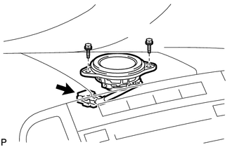
(b) Disconnect the connector and remove the center speaker assembly.
5. REMOVE NO. 1 INSTRUMENT PANEL SPEAKER PANEL SUB-ASSEMBLY
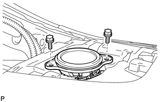
6. REMOVE FRONT NO. 2 SPEAKER ASSEMBLY
|
(a) Remove the 2 bolts. |
|
|
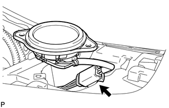
(b) Disconnect the connector and remove the front No. 2 speaker assembly. |
|
7. REMOVE FRONT PILLAR GARNISH CORNER PIECE (for 13 Speakers)
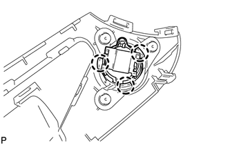
8. REMOVE FRONT NO. 3 SPEAKER ASSEMBLY (for 13 Speakers)
|
(a) Disengage the 3 claws and remove the front No. 3 speaker assembly. |
|
 Components
COMPONENTS
ILLUSTRATION
...
 Inspection
INSPECTION
PROCEDURE
1. INSPECT FRONT NO. 2 SPEAKER ASSEMBLY (for 6 Speakers)
(a) With the speaker installed, check that there is no looseness or other abnormalities.
(b) Check that there is no fo ...
Other materials about Toyota Venza:
Radio Receiver Power Source Circuit
DESCRIPTION
This is the power source circuit to operate the radio and display receiver assembly.
WIRING DIAGRAM
CAUTION / NOTICE / HINT
NOTICE:
Inspect the fuses for circuits related to this system before performing the following
inspection procedure. ...
Removal
REMOVAL
CAUTION / NOTICE / HINT
HINT:
Use the same procedure for the RH side and LH side.
The procedure listed below is for the LH side.
PROCEDURE
1. REMOVE REAR WHEEL
2. SEPARATE REAR DISC BRAKE CALIPER ASSEMBLY
3. REMOVE REAR DISC ...
How To Proceed With Troubleshooting
CAUTION / NOTICE / HINT
HINT:
Use the following procedures to troubleshoot the tire pressure warning
system.
*: Use the Techstream.
PROCEDURE
1.
VEHICLE BROUGHT TO WORKSHOP
NEXT
...

0.1163